Search the Community
Showing results for tags 'dcc'.
-
New DCC Friendly list for Kato. https://docs.google.com/spreadsheets/d/1qRGTOaq-4F89xph3ZxL5iKxM5jptkeoNw77t3X-STY4/edit?usp=drivesdk If you have new data or updates, please reply here and I will incorporate the changes Please keep replies to just updates, if you have installation issues/questions, please start a thread for that model. Thanks, Ed
-
HO Scale Zoukei Mura 0 Series Shinkansen DCC Decoder Help
The Bandwidth Limited posted a topic in DCC, Electrical & Automation
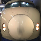
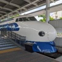
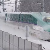
Hi everybody! New to the forum here but I have been lurking for the past few months. My wife and I spent three weeks in Japan from mid-May to early June of this year; jumping from Tokyo, Kyoto, Osaka, Hiroshima, Odawara, and Kanazawa. I have been collecting HO Scale models (mostly modern Amtrak equipment) for years and am slowly building up supplies to construct a layout in our home. So, when we went to Japan, the only thing I needed to purchase as a souvenir was either a modern or iconic Japanese Passenger train in HO Scale. Of course, this forum and some other resources made me realize prior to that trip that N-scale dominates the Japanese market (for completely understandable reasons), so I tempered my expectations before we even got into the country. However, about a week and a half into the trip I felt like I hit the jackpot. I found not just one, but numerous boxes of HO Scale Zoukei Mura 0-Series Shinkansen at a Hobbyland Pochi in Osaka. They had two Basic-Sets, two A-sets, four B-sets, and eight individual motor cars all in their original boxes for sale (see below for a snip of sets available for the Zoukei Mura Shinkansen). After some deliberation with the wife unit about our suitcase situation, I got the green light to purchase a Basic-Set, an A-Set, and a B-set from the Hobbyland Pochi in Osaka. They were all being sold at full retail price despite being used models, however seeing that they were all in extremely good condition (A-A) and the yen is pretty weak to the dollar at the moment I didn't really mind paying retail too much. Fast forward another week, and I found another extremely good condition B-set at a Hobbyland Pochi in Yokohoma for well over half of what I paid for the B-set in Osaka so I snatched up that one as well. So yeah, I really wasn't intending to, but I arrived home back in the United States with a twelve car HO-Scale Zoukei Mura Shinkansen consist that I paid less than $750 for. I still feel extremely lucky and happy that I was able to find and come home with such a beautiful set. Here is where I am looking for some help from this forum... All of the HO American locomotives I purchased prior to this Shinkansen are DCC and Sound equipped from the factory. The future layout I plan to construct will definitely be DCC. In fact, I am likely going to pick up a Digitrax EVOX set this weekend during all the fourth of July sales. So, all that to say, I would very much so love to put a DCC Sound Decoder and Sound System into this Zoukei Mura Shinkansen that followed me home from Japan. However, I have no experience in buying, installing, and configuring DCC Sound Systems into existing locomotives since all my previous models have had DCC Systems installed at the factory. I haven't taken the car body off of one of my Shinkansen models yet, but in my research I saw that Zoukei Mura put provisioning in the motor cars to allow a DCC Decoder to be installed; specifically a LokSound v4.0 Decoder that Zoukei Mura offered for sale at one point complete with Zoukei Mura sound recordings of the 0-Series Shinkansen. The only place I have found any information about that older LokSound v4.0 Decoder was on a Japanese Volks Hobby Heaven online store URL. There are two problems with that Volks page though, the first being that Volks Japan doesn't ship outside of Japan and the other issue is that the Decoder is likely never going to come back into stock again since Loksound has moved to the LokSound v5.0. So, I ended up doing some more research and found that a Hobby Shop/Specialist in Great Britain (Roads and Rails) took it upon themselves to create a sound file for the 0-Series Shinkansen and offer it for sale on a LokSound v5.0 decoder. The Roads and Rails team even created a YouTube video to showcase the model's sounds, and to my uneducated ears it sounds pretty cool. Finally, here is what I am look for help on: Is the LokSound v5.0 Decoder a drop-in replacement for the Loksound v4.0 decoder? (Trying to see if the Road and Rails LokSound v.50 will just be a plug-and-play option or if there is going to be some custom fitting involved with that install) I would love to consist the entire train on a DCC Layoud and have three motors cars: Should I just get three LokSound v5.0 decoders (one for each motor car)? I don't think I really need three sound decoders (two at most), but I'm not well versed enough in DCC Systems to know if I need three of the same, relatively expense decoders in order to make consisting the train easy. Also note that I have never done any speed programming myself and do not currently have the tools and resources to do so. Do you think the Zoukei Mura Shinkansen's motors will be able to handle DCC Pulse Width Modulation okay? Most Japanese Model companies optimize sales (and motors, I imagine) to standard DC because that is what their markets demand. Though, I would like to think Zoukei Mura selected the motors for the 0-Series Shinkansen to be compatible with DCC since they added provisioning DCC Decoder in their motor cars and offered a Sound Decoder for sale at some point. To those of you much more well versed in the 0-Series Shinkansen: How close to the prototype is the Roads and Rails sound files (demo'ed on that above YouTube link)? I'm not a rivet counter but I am curious how prototypical the sounds are. Apologies for the wall of text. However, I don't really have any people close to me that share my love of model trains, so I kind of needed to express to some of those more familiar with the subject material my story of how I got the models and just how elated and fortunate I was to find them! I also obviously am looking for some assistance. Thanks for your patience and your time!
-
 Hi everyone. I’m working on a new open wireless platform to control trains, layout accessories (signals, level crossing), and any movable vehicles on a layout. I call it WCC (wireless command control). Every decoder communicates with other decoders over the air that’s why you need just plug DC power into your layout. No command stations and boosters are required - just install a decoder inside a train or connect a decoder to a signal, open a browser on your laptop or mobile device and you can already control your layout. DCC is still can be used in case you already have a layout with DCC. I would like to get your feedback, and ideas to know what features should be included at the beginning and what later. The protocol will be fully open with code examples so users who like to code can develop their own decoders and controllers. WCC decoders will be available from December 2023 - January 2024, documentation about the protocol with code examples on Arduino and how to develop your own decoder will be available in December as well. Below you can find more details about how it works, a schematic, and a photo of a decoder prototype - production candidate (currently the size is 11 x 39mm, after we release the main version, we'll add special versions for Kato). Also, you can get more info at https://loco.engineering Main features - Two-way wireless communication between all decoders - trains, cars, and layout elements "talk" with each other - Decoder functions, CV, settings, and logic can be changed directly from a web browser - No boosters, additional wiring, command stations, and CV programming required - Can run on DC, AC tracks, and a battery - Detect train location and add complex interactions with NFC tags (for scale N NFC tags (5 mm x 5 mm) should be placed on a train, and readers (small circuits) should be placed under rails) - No vendor lock-in anymore - WCC is an open protocol with clean documentation, code, and hardware examples for Arduino - Loco.Engineering decoders can be used with classic DCC systems, so you can buy one decoder and try it on your current layout - OEM and the white-label app even for small model train manufacturers - The easiest and probably cheapest way to convert your DC layout to the interactive layout - Over-the-air sound and firmware updates - you shouldn’t remove the train case to update sounds and firmware - Everyone is able to create custom controls and throttles - Low-cost - sound decoders cost €50 or $55. You don't need any additional tools to control decoders or to program them. - Designed, developed, and produced in our workshop. Zero outsourcing and full control of development help us to deliver updates and new features very often. - Updates and new features every week, fast friendly support Feel free to leave feedback here or contact at hey@loco.engineering Project's website: https://loco.engineering
- 4 replies
-
- 3
-

-
- dcc
- automation
- (and 2 more)
-
About 5 years ago I did two different Greenmax JR103 setsw power units. These have the coreless motors. I also have and did one older JR103 set from Greenmax but that is not the subject of this entry. Someone posted on Reddit about the MT40 stuff and someone asked if they had any Greenmax compatible units and I said I didn't see any but I had done some wired conversions and could post the pics. I am posting here as my base of operations and for posterity. These pics come from both my conversions, which were done the same, and uses a D&H PD05A decoder. You could really use any micro sized decoder like a Lokpilot 5 micro or a Zimo micro as well. I may come back and provide more text to this but for now, due to time and being late with some day-job work, I'm just posting the pics of the steps I did.
-
Hello, I'm yaasan from Japan. I'm developing DCC command station and related devices. I would like to introduce our great DCC sound Project "OPEN SOUND DATA". This project provides Japanese train sound for free of charge! These sound data requires ESU's LokSound V4 and 5 series as you know. If you have ESU's lokprogrammer and LokSound decoders, you can install it now! English page: https://desktopstation.net/sounds/index_eng.html Japanese language page: https://desktopstation.net/sounds/ Also we are developing "ExpBoard" series which is installation kit for Japanese Train model (Tomix, KATO, Green Max etc.). HO scale board for KATO: https://desktopstation.net/wiki/doku.php/expboardnext18 N scale board: https://desktopstation.net/wiki/doku.php/expboardecn HO scale generic use: https://desktopstation.net/wiki/doku.php/expboardgeneral Please try OPEN SOUND DATA now! If you have a question, let me know. Thank you for interest.
- 67 replies
-
- 15
-
-

-
Warmest Christmas greetings to everyone, This is my first post on this forum, so let me introduce myself. My name is Alex, I am from Kyiv, Ukraine. I had to move to Germany after the war began in my native country. I am collector of Z scale models since 2006 and manufacturer of small series products like train models, digital decoders, load inserts and accessories for Z scale 1:220 under my own brand Zmodell since 2016. Here is my Facebook page: https://www.facebook.com/Zmodelltrains I am also a member of Z scale International Forum (Germany) and AZL forum (USA): https://f.z-freunde-international.de/memberlist.php?mode=viewprofile&u=1508 https://azlforum.com/user/565 I am also a member of Trainini Team - German online magazine about Z scale model trains: https://www.trainini.de/team And of course, I am a big fan of Japanese Railways and owner of one of the biggest collections of Z scale 1:220 Japanese trains in Europe. My collection counts numerous models from such manufacturers as Rokuhan, Tenshodo, Prmloco, Platz/F-Toys, ZJ Gauge, Akia and others. In 2019, I started developing my own digital decoders based on Doehler & Haass and ESU technology - solely for the needs of Z scale models from Märklin and AZL. In this report I would like to introduce my next development – sound decoder for Rokuhan trains. After successful development of the sound board for Z scale Marklin V320 diesel locomotive (Art. No. 88320 and 81320), based on the newest and the smallest sound decoder from ESU – LokSound 5 Nano, many new possibilities of equipping Z scale models with sound features became clear to me. Report about my sound decoder for V320 locomotive can be found here: https://www.facebook.com/100063508513124/posts/pfbid0hbX6d949KEs1mwF76HsiNUcmNHzTmvsr15bAkAJEPV3oWgp7urmzMiq2BeMihWVZl/ One of decisive factors that brought me to the idea of developing something for Japanese trains became the availability of prototypical sound projects for ESU sound decoders created and provided for free non-commercial usage by Desktopstation.net – Japanese provider of open-source DCC hardware and software that supports and sponsors creating of prototypical sound projects by railway enthusiasts in Japan. The list of sound projects is available here: https://desktopstation.net/sounds/list_eng.html While multiple unit trains is not the strongest category in Märklin’s product line, it is a major part of the whole lineup of Rokuhan rolling stock products. Furthermore, Rokuhan already showed, let me say, more progressive way of thinking in comparison to Märklin in terms of introducing digital control to Z scale. Digital command station and a number of different digital decoders for rolling stock and accessories already exist in Rokuhan’s product line. I have to admit that these products are not ideal in their current generation (especially in comparison to modern competitive products from German manufacturers), but they fit quite well within the needs of railway hobbyists in Japan, and in any case, it is better than nothing at all. One of the popular digital products of Rokuhan is a universal DCC board (Art. No. A059) that fits into all types of their passenger cars, cars of multiple unit trains and single running railcars (aka railbuses). A059 board features one good advantage: it actually combines two different devices together – locomotive decoder and function decoder for interior lighting. I fitted all Rokuhan trains in my own collection with these digital boards. As I have already mentioned above, availability of the prototypical sound project for Shinkansen 500 Series high-speed train and a number of other projects for Japanese trains existing in Z scale inspired me to start this development. And my idea was to develop a universal solution (just like A059 board from Rokuhan) which would fit into the maximum possible number of models. After making all necessary measurements of different train models, I developed the following specifications for my new digital sound board: - It will exist in two forms – long and short (corresponds to types A and D, according to Rokuhan’s specifications, see details here: https://www.rokuhan.com/products/wp-content/uploads/2022/01/A053_A059_DECODER_INSTRUCTION_MANUAL_E_f_18.4.10.pdf). Short form is derived by manual cutting off the long board; - Long form for will be suitable for the motor cars of Shinkansen 500 Series (Art. T013-x) and 0 Series (Art. T020-x) high-speed trains; - Short form will be suitable for the motor cars of the following trains: Tobu 500 Limited Express Train “Revaty” (Art. T034-x), JR 103 Series (Art. T022-x), JNR 113 Series (Art. T001-x, T003-x), JNR 115 Series (Art. T011-x) and JNR 415 Series (Art. T023-x) commuter trains. Very thin motor chassis and extremely silent driving gear are great advantages of Rokuhan trains which contributed for this development to become successful, too. The only train where it turned out to be impossible to fit the sound board is Shinkansen E6 Series – unfortunately, its cars are too small and offer too less available space inside. Also, my board is not compatible with Rokuhan’s Kiha 52 Series railcars due to the specific mounting requirements – different circuit board is needed for this type of the car. By the way, prototypical sound project for Kiha 52 is available at Desktopstation.net, too. I equipped my digital sound board with highly-effective energy storage module that has been already used in my sound decoder for V320 diesel locomotive and proved its efficiency. It is based on 2x 470 µF/16V Tantalum-Polymer capacitors and features overvoltage and thermal protection. I used the same type of the loudspeaker from V320 sound decoder – 15x8 mm model with only 1.5 mm thickness and 32Ω impedance. Luckily, ESU sound decoders support 32Ω speakers (unlike D&H models which require only 4-8Ω models). I prepared two different types of sound boxes – 1.5 mm and 2 mm thick. They are made from clear polystyrene on CNC cutting machine and airbrushed with clear lacquer in order to make them more transparent after CNC processing. Thick 2 mm soundbox is used in long sound board suitable to Shinkansen trains, while 1.5 mm one is used in short version suitable to everything else. I have to admit that I was very impressed by the quality of the sound and its loudness – all this was successfully achieved without any problems, despite very small size of the loudspeaker and soundbox. Choosing the right LEDs that would match the color temperature of the LEDs used in original Rokuhan A059 boards became a very challenging task. For some reason, Rokuhan uses cold white LED in their boards. I tested many different LEDs, and the only suitable model that provided nearly identical color temperature became white LEDs from Osram with 8200K color temperature. So, here are my new digital sound boards. This is the long version – with ESU LokSound 5 Nano sound decoder alongside and new E24 socket visible: And here is a comparison to Rokuhan A059 board cut off to the same size (Type D): The bottom side: You may notice that I used gold plating for my circuit boards, unlike Rokuhan. Also, I added “LV” and “LR” soldering pads for connecting headlights and tail lights connected in anti-parallel – for possible non-standard usage scenarios. And here is the short variant, derived from the long one by cutting: Comparison to Rokuhan A059 board (Type A): Here are the installation samples. Everything is pretty easy here – just like with original Rokuhan digital or analog boards. This is how the sound decoder looks when installed into the motor car of Shinkansen 500 Series high-speed train: Tobu 500 Limited Express Train “Revaty”: JR 103 Series commuter train: JNR 113/115/415 Series commuter train: I have prepared a series of videos demonstrating sound features of different Rokuhan trains equipped with my sound decoders. Once again, all sound projects for all shown trains are prototypical. Note: all non-motor cars in all trains shown in the following videos are fitted with Rokuhan A059 digital boards: Shinkansen 500 Series high-speed train: Tobu 500 Limited Express Train “Revaty”: JR 103 Series commuter train: JNR 113 Series commuter train: JNR 115 Series commuter train: Notice about Shinkansen 0 Series recently announced by Rokuhan: although my digital sound board is suitable for this train, no prototypical sound project available for it. And it is impossible to create it, since these trains are not in service since 2008. Nevertheless, I will try to dig into the subject a bit more and probably to find the closest matching sound project for this train, too. I will post an update here and add a demonstration video, too. Best regards, Alex, Zmodell
-
Kato DCC Install on 800 Series Shinkansen and Sunrise Express
BulletTrain816 posted a topic in DCC, Electrical & Automation
I came home from Japan with a bunch of EM13 decoders and an 800 and Sunrise. The shopkeeper that I could install DCC on the trains and I presumed that it was a drop in EM13 like all the other trains. When I got home and opened it up I was met with a surprise which was that there was no drop in. Can I hardwire to EM13 to the pickups or do I need to get another decoder? -
Can I install DCC on a Poppondetta Tokyo Metro 1000 Series
BulletTrain816 posted a topic in DCC, Electrical & Automation
Poppondetta produces some trains however due to its obscurity there is no info on how to install DCC or if there is any decoder that fits it. Here is the link: https://maker.popondetta.com/maker/?p=555 -
Hello, I’m getting ready to convert my only other Tomix train to DCC, a single KiHa 40. Opening it up, the LEDs are different from what was inside the 700 Series Shinkansen. My problem is that I don’t know which end is positive. Both the LEDs and the board are marked with a small line, visible in the photo below. I don’t know if that’s supposed to be a “-“, to indicate the negative side, or just simply a visual aid for assembly at the factory. Anyone else have experience with these? I could also use suggestions for wiring and board modification. I’ll be installing a Digitrax DZ126T.
-
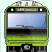
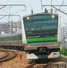
What DCC decoder is compatible with the Kato Yamanote Line E235 (N)
BulletTrain1805 posted a topic in DCC, Electrical & Automation
I am looking to buy a decoder for my E235 I have looked through multiple forums and not found a thing, does anybody know? -
Hey guys, So, after a few months of planning and thinking, it's finally time to start building this baby! Tomorrow I'll go buy all the material needed for the wooden base and in the weekend I'll start building it. This is the final layout: Since it will go into my living room, and it will be 2.40m long, it will be divided in two parts, almost in the middle, so it will be easier to handle. The base will be of plywood, 1.5cm thick, reinforced with 3x2cm frames. Since the forniture has a Wenge-like color, I'll paint the whole base of a dark color. From below, it should be something like this: The two 45 degrees corners in the front are due to the fact that the 70cm deep base will go against a 60cm deep cabinet, so I'll to cut it in order to avoid hitting my leg every time I walk by. It will go here, below the TV, on an IKEA Besta bench : The TV will limit the space above, I'll have around 30cm to play with, but it should be enough. I'll make videos detailing all the process, which will involve a lot of trials and errors I'm sure, as this is my first build, but that's the fun part! Here's the introduction video:
- 25 replies
-
- 6
-
-
- tokyo
- tokyo station
- (and 3 more)
-
Hi! I’m wondering if the Kato 10-354 takes an EM-13 and FL-12? Thanks!
-
After the experience I got with my first layout on tables back in August, I bought some more of Ikeas Lack tables for my next thing. This time, I wanna try a different approach, as I still need my GFs aproval for some of the tables I put in the livingroom (mostly because of manouverabilty and easy of access for the couch) and try to get some general ideas what I wan't and could do. And in contrast to my FAST-Layout for Shinkansen I built last time, with a simple loop, I wan't to get point to point operations going with DCC. Features I want: - Commuter layout for 10 car trains - 2 Stations (in the operation sense, with switches and parking spaces for 5, 10 and 11 car trains) - one or multiple stops for 10 car trains - single track extension of a line continuing of one station for at leas 5 car trains - may contain bridges - may contain viaduct stations I already made a first draft of what could fit, and also have some photos of the tables setup.
- 73 replies
-
- 4
-
-
- console city
- unitrack
- (and 1 more)
-
Wiring Kato turnouts and double crossover for DCC, occupancy detection and automatic control
williamv posted a topic in Layout Planning
While I wait for my Unitrack to arrive, I've started planning the wiring. I'm hoping someone can help with the turnouts. Please forgive me, I'm new to the hobby and I'm still learning. I'm wiring it for DCC, and I'll be using Digitrax. I'll be using occupancy detection, also Digitrax. In my track plan, each coloured section is a detection block. The purple lines show where I intend to power the tracks with terminal unijoiners (power to each detection block not shown). I intend to control the layout with TrainController. My understanding is that I do not need to isolate my turnouts (Kato #4), as long as I set them to non-power routing, with the frog set to insulated. There seems to be some confusion online about power-routing vs. non-power routing labels but I'd be setting so them so that all rails are powered, regardless of switch position. I've isolated my turnout sections, only for the purpose of occupancy detection, with a block on either side of the turnout. I'm slightly unsure about where to connect the track power for the turnout. At each end of the turnout, I have a separate detection block, which I need to isolate from the turnout. Q. If all rails are live, and the frog insulated, could I connect the power at any end of the turnout? Then I come to the double crossover, which is what has me confused. I believe that I need to power each of the 4 ends of the crossover. However, I have blocks on either side of the crossover, so I would need to isolate the double crossover from the adjacent blocks, so where would I connect the power to the crossover? I suppose I could add a short Unitrack piece (S62) on either side, then I could connect the power at the joins between the crossover and the S62, then insulate at the join between the S62 and the next piece. Unfortunately, I'm already at the edge of the layout, so I can't afford to extend the track plan. Q. Have I understood this correctly? Do I have any other options? Is it best to keep the crossover and turnouts between blocks, or can they be in the blocks? Thanks for any advice!
-
Making a 14 Guage Wire that Can Plug into the DCS50K
Gilshrat posted a topic in DCC, Electrical & Automation
So I am using a DCS50K (Kato Part No. 29-119) DCC system to run my Japanese train layout. I currently am using the standard wire connectors and splitters that come with Kato track (Item No. 24-825 & 24-827). However, I am having issues with power drop and poor DCC single pick up by some of my locomotives. These wires use 22 gauge wire which is considered thin for a standard DCC power bus. I am thinking of making my own power bus using 14 gauge wire. However I need to make a custom plug so I can connect the power bus to my DCS50K. Does anyone know if you can purchase uncrimped versions of the plugs used by Kato so I can make my own power cables? If you can, what are the called and who makes them? Part number? Thank you in advance for your suggestions and help.
-

Has anyone installed a sound decoder into their Kato Shinkansen?
GeorgeHInch posted a topic in DCC, Electrical & Automation
I'm curious if anyone has added DCC sound decoder to their Kato Shinkansen, specifically the E7 or N700A. I saw a thread on here from back in 2015 that started addressing this but it seemed to end very anticlimactically due to limitations at the time. It seems like the non-motored trailer cars for the N700A have a cavern under the floor piece with a metal weight. Since the metal strips already run through here it seems like an easy place to stash a sound decoder with a sugar cube speaker. I assume a decoder and speaker will come close to weight to the metal already there. I think the biggest question here though, has anyone ever generated sound files for any of the Shinkansen? -
Just to share with you how I converted the Kato 103 series Yamanote line train to DCC. I am not claiming that this is the best, the only or even a good way of doing it but it worked! The Kato 103 series is not at all DCC friendly so it took a lot of disassembly, soldering and re-assembly, and of course adjustment of CV values. Maybe not something for the faint-hearted. For the motor car, I used a Kuehn N45, simply because it is small, can handle the motor current and it was readily available at the shop I bought it. To make sure that I got the wiring right, I marked the forward direction and left and right side of the car. The carriage needed complete disassambly and the copper strips connected to the motor needed to be bended upwards to allow soldering of the wires. Same for the left and right hand rail power busbars. I do not solder on these strips while assembled in the carriage to prevent damaging (melting) the plastic parts. Initially I had the carriage lighting simply run on rail power, as recommended by Ken Shores of the famous http://www.sumidacrossing.org. That worked fine on my N700A Shinkansen but the 103 series has large windows and the whole thing looked way to bright. However this decoder has no wire leads for interior lights. Instead I connected the white lead, normally used for the front lights, to the Kato interior LED assembly. That could easily be done because this carriage sits in the middle of the train and does not have front nor rear lights. I needed to reconfigure the front light controls to become interior lights (function mapping to F1) and adjust the dimming to a mere 30% of the full brightness. During testrun I found that the train runs way too fast. Some 350 scale-km/h easily! Real slow running was difficult. So I lowered the default start value to the very minimum and halved the max power value. Obviously this is decoder dependent. Because the decoder is quite small (and flat) it does not appear visible behind the windows. The front and rear carriages are wired up with Doehler & Haass FH05B decoders to control the head and tail lights. The Kato 103 series still has old school light bulbs for front and rear lights, assembled with diodes on a small printed circuit board. To wire the decoder to the lightbulbs, the diodes needed to be removed. To dim and control the interior lights the KATO LED assembly is wired to the Aux 1 connection of the decoder and function mapped to F1 key. Again the interior light LEDs are dimmed to 30%. Now the other carriages still had their interior light run on rail power. So these needed to get their own decoders. In this case I soldered the decoder red and black leads to the clips that power the interior lights. To do that two small holes needed to be drilled in the bulkhead in front of the LED assembly. At the right, the holes in the bulkhead are just visible (where the red and black wires run through). All decoders in the train have the same DCC address, just to make it easy to control everything at the same time. So all lights go on and off at the same time. Not sure if that is prototypical. Maybe in reality someone is walking through the train and switches on/off the lights of the carriages one by one. In that case I could reconfigure everything to turn the lights on and off in a staggered way through iTrain. The complete train (with one carriage missing because otherwise the train would be too long for my testtrack) Another thing is that with lights on, the train is obviously empty, without passengers. Maybe I should now add standing and sitting passengers, e.g. by having a PS sheet fitted with figures glued to it. Of course the figures will need to be cut at their waist to get their heads at the right level behind the windows...
-
Hopefully somebody already solved this riddle and can help me! I started to convert my lay-out to DCC control and doing tests with and playing around with DCC control using my N700A. Now I am at the stage to plan ahead and check how to convert my other rolling stock. I have small electric locomotive, the KATO ED75-700 (Kato 3075-3) that is not DCC friendly. In another topic I found that a similar model (the Kato 3075-1) may be fitted with the Digitrax DC163K0A. Does anybody know if this decoder may also be fitted in my 3075-3 ? Many thanks! Jan
-
Hello - Its been a while for me on this forum but, as you know, life gets in the way. Anyway, I recently received this 6 car set thinking i would enjoy the fact that i could drop-in the Cab and Motor DCC decoders and off we go. The motor car install did not go as planned and it was at that point i discovered Sumida Crossing describing the exact same issue - DCC Kato Ginza - which is the EM-13 does not sit properly once slid into position (that lump of metal and the nibs between the motor and the truck slot prevents a flat seating.. You can also see from the pictures that, even after trimming the EM-13 width to clear the sides, I can not get the truck back on. So it looks like i will have to wire in a decoder - possibly a small LokPilot. Anyone have any advice for wiring a motor decoder in the Ginza Series 01? Also it looks like the motor is protected by a plastic piece that i will have to remove to get to the motor contacts. Im hoping that it just pops off if anyone can verify if they've done that before. Thanks and happy motoring, Peter
-
I am seeking a bit of direction from the real experts amongst you! My lay-out is approaching completion with the scenery almost done and the trains running analogue. Few things still need to be completed but it is time to start wondering and thinking about the next steps: Equip my trains with DCC and operate them through a PC. There is an overwhelming amount of information available in the web, even on the forum. I have no idea where to start. The webpages of product manufacturers are overwhelming and confusing at the least. They advertise bits and pieces with datasheets without any easily comprehensible information on how to put it all together. E.g. Digikeijs and DigiTrax websites are hard to interpret. E.g. what module do you need to control the Kato turnouts? I do not have a huge lay-out. Currently there are 3 electrically separate loops with only 5-6 trains on it at any moment and only 3 driving at the same time. The photo's give an impression. I have a few dreams/wishes: I like/need to avoid complete re-wiring and partitioning of the tracks. JR style signals are controlled by the DCC system. Trains run a sort of time table automatically (by the PC) and nicely accelerate and decelerate prototypically. There is sound from the station with the JR tunes, whistles, brakes, announcements. Specific questions I have: I understand that it is nowadays possible to 'tune' the PC program such that the speedsetting of the train matches the actual speed. The software corrects for the normal differences between trains. Given that the PC sets and 'knows' the speed of the train, it continuously predicts where the train is with reasonable accuracy. This allows the PC to have a train stop at the platform without the need for train detection at every point you may decide to have your train stopped in future. Avoids a lot of wiring. Of course there is a need for a few detection points to reset the position calculations. a) Is my understanding correct? b) What PC software does that? What popular /affordable module(s) can be used to control the KATO 2-wire turnouts? They all seem made for 3-wire 2-coil turn-outs. Where can I find Japanese style signals that can be controlled by the DCC system? What about sound, either built into the KATO trains, or by having small speaker fitted under the station to have the PC generate the appropriate sounds (whistle, doors, announcements, the famous JR tunes, etc.) ? Are PC programs available that allow that to be added? Any help or directions y'all can give?
-
I recently received the Kato N700A 4-car set and installed the DCC decoders in the cab cars and the power car. I was considering adding a DCC sound decoder into the non-powered car. I believe there should be enough room under the floor plastic if I removed the metal weight. I'm curious if anyone knows of or has created any sound projects for any of the Shinkansens yet.
-
- 1
-
-
- dcc
- soudn decoder
- (and 1 more)
-
Does anyone know of a good website with a list of Kato Japanese locomotives and their corresponding "drop-in" decoders. All the lists I can find are only for their NA models, but I know that many of the light boards used in NA models are also used in the Japanese models and therefore there are compatible decoders out there for many Japanese models as well. Thanks
-
Hi I've bought some Kato Unitrack to run my US HO and UK 00 scale stuff on. I'd like to buy a Bachmann Dynamis for my DCC equipped locos to run on, but I'm stumped on how I can connect the track to the controller? Presumably the Kato wire only fits the Kato controller.
-
Hi every one which dcc decoder I can use with KATO EF57?
-
Hello all, I have been adding the detail parts and dcc'ing a Kato ef58 that i've had for some time. When I took the body off, I noticed that there are guides above the cabs for tail lights, as well as the headlights. Shining a light through the body confirmed that the light was delivered to the lenses for the tail lights, so I set about adding some leds to illuminate the tail lights, as there is space to do so. Inside the ef58. LEDs can be added to the grey box at either end of the model. I used 3mm LEDs, pre wired with a resistor. Grey box removed. The guide for the headlight lens goes through the gap on the left, you need to drill a hole on the right hand side for the light to pass through.