velotrain Posted February 19, 2015 Share Posted February 19, 2015 I suspect relatively few are using under table wiring, but I'm wondering how those that do handle the turnout wires? It looks like you would need to drill a 1/4" hole (and perhaps file it out some) to clear the connector. The other option would be to cut the connector off and solder your own wires. I suppose the same applies to Kato also. Link to comment
kvp Posted February 19, 2015 Share Posted February 19, 2015 The Tomix connectors are much smaller and could fit though a small hole. These could be drilled right under the turnouts and plugs to hide them. Tomix connectors are mostly raster sized, so it's possible to make terminal strips for them on raster boards. Also possible to aggregate the cables into ribbon cables. This is why it's better to keep the connectors and make extension cords at home. Link to comment
ozman2009 Posted February 20, 2015 Share Posted February 20, 2015 When you do drill your holes, use short sections of plastic drinking straw to line them. They make it much easier to thread the wires through. Link to comment
mrp Posted February 20, 2015 Share Posted February 20, 2015 To easily experiment with different layouts and wiring, I’ve been using an outdoor table from IKEA. It works really well. The Tomix connectors just push down between the slats. I have to laugh when I see the wiring examples in Tomix catalogs. How on earth can anyone get their wiring to look as neat as that? Even running a couple of wires under a piece of track is hard enough. I guess they have a team of tabletop wiring experts that spend hours setting up each shot. Or maybe they photoshop the wires in later… Link to comment
zartan Posted February 20, 2015 Share Posted February 20, 2015 That table is a great idea MRP. What are the green PCBs I see around the layout? Signals? What type? Link to comment
kvp Posted February 20, 2015 Share Posted February 20, 2015 I guess they have a team of tabletop wiring experts that spend hours setting up each shot.You would be surprised a little bit of hotmelt glue can help a lot getting the wires to stay where you put them. It's also mostly removable with some scraping. Signals? What type?Those are MRP's brand new and quite innovative signals. They are part of a complete signalling and control system. Link to comment
mrp Posted February 20, 2015 Share Posted February 20, 2015 What are the green PCBs I see around the layout? Signals? What type? Hi zartan, As kvp says, they’re part of a project I’m working on. If you’re interested, I’ve been posting progress reports to the Signal Project thread under Personal Layouts & Projects. (And thank you for the kind words, kvp!) Link to comment
cteno4 Posted February 21, 2015 Share Posted February 21, 2015 Another great wiring tangle saver is a roll of double sided Velcro and a staple gun. Just staple a 2" piece about 3/4" from one end and then you can just bundle wires ans wrap the Velcro around them. Tack up a grid of them and as you wire and retire and fiddle you can easily reconfigure until you have things figured out, the come back and do some better wire fasteners if you want to. Jeff Link to comment
velotrain Posted February 21, 2015 Author Share Posted February 21, 2015 Thanks for the info guys. kvp - "The Tomix connectors are much smaller and could fit though a small hole." I measured them and that's where I got the 1/4" from. They're 4x6 mm at the interface, and close to 7 mm on a diagonal across the corners. Link to comment
kvp Posted February 21, 2015 Share Posted February 21, 2015 The Tomix connectors are much smaller and could fit though a small hole. I meant they are much smaller than the Kato ones, so you can actually drill a hole for them. This is why the plugs have a round top profile, so they can fit through the hole. The cable connection points of plugs and and switches allow routing straight down, so you drill under them and the hole with the cable will be 100% invisible from the surface. Link to comment
The Next Station Is... Posted February 21, 2015 Share Posted February 21, 2015 EZ Twist Locks (http://www.usplastic.com/mobile/item.aspx?itemid=23169) are a favourite of mine for keeping bundles of wires together. I think you get get ones with sticky pads as well to attach them under boards. Link to comment
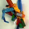
velotrain Posted February 21, 2015 Author Share Posted February 21, 2015 I had a question on something else and will post it here, so I don't start a new topic. I'm close to getting a Tomix dual throttle controller and TCS. I gather from the programs that it controls two turnouts at maximum, and am reasonably certain these plug directly into it. I would like to have the ability of alternating between 2-3 programs, but don't want to have to change the turnout leads each time. The obvious solution is an interface panel/board where I can vary which turnouts are currently connected to the TCS. I don't think I'll need to vary where the track power is going, but if I do I'll need to switch where the TCS output is directed as well. Having only a vague idea of how the TCS functions, am I misunderstanding anything here? Also, is there a Tomix compatible plug/socket available from elsewhere, or will I need to modify Tomix products to get longer cables, etc. Lastly, here is a photo showing the opposite of the Tomix obsessively neat wiring. No wonder they're hiding it from the public. Link to comment
mrp Posted February 22, 2015 Share Posted February 22, 2015 (edited) If you are talking about the Tomix 5563 TCS Automatic Operation Unit, as far as I know it’s not really a manual throttle. I think you’ll need to purchase a Power Unit/Controller separately. Here’s the back of the 5563: The connectors - from left to right - are: 4 x TCS Sensor inputs 2 x DC Feeder outputs 2 x Points outputs 1 x TCS Accessory Power output 1 x DC Feeder input (from Power Unit/Controller) 1 x TCS Accessory Power input (from Power Unit/Controller) Tomix use 4 types of connector: 1) DC Feeder - white connector and socket embossed “F”. - 12V analog or PWM (if CL lighting) track power 2) Points - black connector and socket embossed “P”. - 12V pulse to change points 3) TCS Accessory power - black connector and socket. - 12V DC output to power accessories 4) TCS Sensor input - 3 pin miniature connector and socket. - two opto-coupler outputs - forward and reverse direction (1), (2) and (3) all use 0.1” connector spacing, so you can plug them into standard PCB pin headers. You can’t purchase just the connectors - they’re a proprietary design manufactured by Tomix. Also, they are have slightly different shapes so you can’t accidentally plug them into the wrong socket. (4) is a standard miniature 3-pin Molex Picoblade connector. I think a challenge reconfiguring the track for the different patterns will be how best to handle the TCS sensor wiring. As far as I know, you need to place a 5559 Sensor Track (or 5558 Sensor Plug) whereever the train needs to stop or change direction. Edited February 22, 2015 by mrp 1 Link to comment
velotrain Posted February 22, 2015 Author Share Posted February 22, 2015 Thanks for all the info MRP. I know I need to buy a separate power pack/throttle ==>> "I'm close to getting a Tomix dual throttle controller and TCS" I think I will only need one track feed, using the power routing turnouts to control operation. I know I will need some longer wiring for the turnout control, but am hoping that I can just splice it in between the connectors. I hadn't considered the need to also control the sensors, as I was planning to have 2/3 sets of them for the varying operation options, but I don't think that in any of the three modes I'm considering, the currently operating tram would cross the sensors of the other modes. If there were maybe 8 sensor input connections, I could possibly keep all of them connected all the time. I can see how needing to select those along with the turnouts for each operation would start to make it very messy. I thought it would be easy enough to externally select which of the turnouts I wanted to use, and connect those wires to the points connectors on the TCS. The sensors appear more complex, as it seems likely that each of them used for any of the operation modes would need to be connected to a different connector on the TCS, which means that I would need to be very careful in arranging them, and the wiring would be much more complex with the 3-pin system. I'm starting to think that it would be better to just wire each operation mode separately, and change the connectors as needed. Perhaps I could permanent mount all of the plugs for each one on a board, spaced/aligned so that it would just be a single function to unplug one and replace it with another. I'm convinced that I should buy everything I think I'll need and "play" with it to understand how it works, and then consider my options. One consideration is that I plan to start with a tram yard module, which contains a loop and also the possibility of limited linear running - I like the idea of the 3 tracks/trains to a common reverse section option. However, I expect to add more modules later, but that may just mean additional sensors. Link to comment
velotrain Posted February 22, 2015 Author Share Posted February 22, 2015 I just had another realization - it appears that both the sensor track and the sensor plug require a certain amount of space next to the track, meaning that you could not easily use them on adjacent tracks. Is there any possibility of somehow angling the "module" on the plug up at 90 degrees so it doesn't need so much real estate? Link to comment
mrp Posted February 22, 2015 Share Posted February 22, 2015 As long as you’re using standard Tomix 37mm center-to-center double track spacing, the sensors are designed to fit ok. Link to comment
mrp Posted February 22, 2015 Share Posted February 22, 2015 The other thing worth keeping in mind is that because the TCS sensors are an “open collector” type of output they can be easily chained together, with the sensors acting in parallel. Each sensor track (or plug) has an additional 3-pin Molex PicoBlade socket for that. Also, the sensors have different outputs for forward and reverse train direction - although I have no idea if the 5563 TCS Automation Unit makes use of that. Link to comment
katoftw Posted February 22, 2015 Share Posted February 22, 2015 some sensors go under the track on the newer tomix stuff. Link to comment
kvp Posted February 22, 2015 Share Posted February 22, 2015 For wiring, i would use a rotary switch with a M to N maping, so one that can switch M circuits in N steps. Then connect the common connectors to the TCS unit and patch each sensor and turnout connector to the M inputs as needed. This way you could select one of the modes on the TCS, the same mode on the rotary switch and everything is wired up. If you want to use 3 programs, then you'll need a rotary switch with N = 3 and M = 12 (or less if you don't use all 4x2 tcs sensor channels or all 2x2 turnout outputs) You can have a separate selector for the turnouts if you can't get a 12 circuits rotary (that would only need 3x8 for sensors and a 3x4 for the turnouts). An easier to source alternative would be to get larger D-subminiature plugs and wire the patch on those. One plug can be fixed with all TCS, sensor and turnout wires routed to separate pins with the other plug exchangable and containing only the jumper wires for each mode (and optionally covered with a plastic plug housing to look nicer and have a place to put the program labels). Example: patch sensor 1 output on pins 1 and 2 to TCS input 1 on pins 10 and 11 and turnout 4 on pins 21 and 22 to TCS turnout output 2 on pins 34 and 35. (the center grounds could be left connected together constantly). Link to comment
velotrain Posted February 22, 2015 Author Share Posted February 22, 2015 The other thing worth keeping in mind is that because the TCS sensors are an “open collector” type of output they can be easily chained together, with the sensors acting in parallel. Each sensor track (or plug) has an additional 3-pin Molex PicoBlade socket for that. Also, the sensors have different outputs for forward and reverse train direction - although I have no idea if the 5563 TCS Automation Unit makes use of that. mrp - thanks for the reassurance on the sensor width. As for reversing, TCS program #5 seems to suggest that this is employed - unless I'm misunderstanding you. As for the chaining, I'm not comprehending what sorts of situations that would be used in. Link to comment
velotrain Posted February 22, 2015 Author Share Posted February 22, 2015 kvp - I've realized that I need to find a course on remedial electronics somewhere. I remember building a radio shack transistor radio as a teenager, but that was over a half century ago. Being in a major urban area, I'm sure I can find something suitable. Your mention of a rotary switch is how I had originally imagined this, but doubt that I have the skills to implement it at present. I'm now thinking that I may start with a less sophisticated set-up, and then go from there. I plan to use the "alternating trams on a loop" mode, but starting from two different locations (storage yard or maintenance building) and am thinking that perhaps I could use a more simple switch to control the two pairs of turnouts, and could keep all of the four sensors always plugged it. The TCS program would be the same, and I could flip the turnout switch at the same time as I manually throw some other turnouts - sending the trams down a track with no sensors on the other side of the loop - to make this possible. As mentioned, I'm now convinced that I need to obtain the components and then see what I can do with them. Thanks to all for the suggestions, but some of it has gone over my head. Link to comment
mrp Posted February 22, 2015 Share Posted February 22, 2015 As for reversing, TCS program #5 seems to suggest that this is employed - unless I'm misunderstanding you. As for the chaining, I'm not comprehending what sorts of situations that would be used in. What I meant was, the TCS sensors recognise if a train is going forwards or reversing and send different triggers. But thinking more about it, I guess the TCS Unit will use that capability in all cases where the train stops, then immediately reverses back over that same track and sensor, in order to avoid just stopping again. As for chaining - it’s difficult to find examples, but here’s a ridiculously complicated one (unfortunately in Japanese). You can see they’ve chained two sensors to the S4 input (plus two points to each of P2 and P1) in order to make more complicated patterns. Here’s some links to the pages with more details and pictures of the layout. http://rtmrw.parallel.jp/laboratory/lab-report-05/lab-05.html http://rtmrw.parallel.jp/layout/rtm-tokai/rtmtokai-3.html There’s even a small video of it running automatically. http://rtmrw.parallel.jp/laboratory/lab-report-05/akaidesha.mpg I don’t claim to understand most of it myself - but I do find it interesting to see what they’ve managed to get the TCS system to do with a bit of effort. Link to comment
kvp Posted February 22, 2015 Share Posted February 22, 2015 Actually there are 3 sensors on S4, two sensors from the foothills station (4) and one from the inner city station (5). Three turnouts are hand switched, one at the foothills station for swappin trains by hand and the two connecting ones at the main station, only usable for stock movement between the mainline and the tram line in manual mode. The video shows program 3 and uses only a single tram, running in a Z pattern. First the top horizontal line of the Z is passed back and forth, then the slope going to the foothills station, then the bottom horizontal leg (back and forth) to the summit, then back on the slope to the main station. This is a classic Hakone Tozan like switchback pattern. The 2nd pattern described on the site uses program 5, first central station platform 1 to foothills station, then back, central station platform 2 to foothills station and back, then summit to foothills and back. The light brown and blue turnouts are not used at all in automatic mode. The dark brown has no function and could be replaced with a straight section and a buffer stop at the inner city station (but it's useful in manual mode for looping around). The two tracks at the foothills station is seen as one by the TCS and can be switched only manually when both tracks have a train stopped on them, otherwise the TCS gets confused. The trick behind using two programs without recabling is that one doesn't effect the other, like for example pattern 2 also switches the inner city route turnout when the tram comes down from the hilltop, but since it doesn't go near that area, there is no problem that the turnout is set against it. 1 Link to comment
velotrain Posted February 23, 2015 Author Share Posted February 23, 2015 I won't even try to understand this "ridiculously complicated" example. I believe Rich K previously posted an example using three urban blocks (street - not electrical ;-) This style of layout is known in the U.S. as a "spaghetti bowl" - for obvious reasons. I'm sure it is very impressive to see the automated operation in person, but it isn't what I am interested in. Here is the current design for my terminal module. I know this is incomplete, but I am planning to use flex track for the straight sections. I would like to use program #5 with the three tracks in the center enginehouse. Initially, the trams will run "the wrong way" around the loop to the upper yard and then reverse. When I add other modules off the bottom right, they will run the correct way, running halfway around the loop on their return - possibly taking the inner wash/cleaning track on the left end. I also thought to use program #7 from two locations, the upper yard and the maintenance building at the bottom. Except for the two stub tracks behind this building, I believe I only need to attach track power between the two opposing turnouts in the top left hand corner, and can feed all tracks using the turnouts. I will need seven sensors if I try to do all of this, but am now thinking that I might start out with just program #5 or #7. If #5, the 4th sensor will be one of the upper yard tracks. If #7 from both locations, I will need a switch (DPDT) separate from the TCS to select which pair of turnouts I want to be operational in the program. Turnouts leading to the sensor tracks will be thrown manually. A major reason for wanting this semi-automated operation is so if I take it to a train show, I can start it and walk around without needing to be running it manually all the time, or just having the same tram running in circles all day. I suspect the #5 program might be the more interesting, as it would involve 3 vs. 2 trams, and include reversing. I'm thinking the switchback program might be good to use for a mining operation, where the mine cars are loaded at the top of the mountain (hill) and then brought down to the bottom for transfer to a truck, another train, or barge. One possibility would be to make the mine train HOn30, and have it transfer (imagined, unless you want to automate this) to a standard gauge HO train. Fleischmann used to make (oversize) N-scale V-tipper cars, and a mechanism for tipping them - shown at bottom left here: Link to comment
velotrain Posted February 23, 2015 Author Share Posted February 23, 2015 kvp - I’ve looked at this and think I basically understand it, but have a few questions. > The video shows program 3 and uses only a single tram, running in a Z pattern. First the top horizontal line of the Z is passed back and forth I’d like to think that if it started at the “first destination”, it would run from there to the main terminal, then up to the foothills? To me, “the top horizontal line of the Z is passed back and forth”, is not a true Z pattern. I would understand the return from the summit to foothills as the start of a new Z cycle, but apparently that is not the case. Actually, looking at the Tomix TCS program diagram, I see that the start point is shown at the first turnout of the Z, so apparently what Tomix had in mind does not match up with a real switchback situation, where you would start at either the top or bottom, and not in the middle. Is there any way to trick TCS into running this as a true switchback by placing the train at one terminus of the Z, or by some other method? I don't know why the main station switch and track 2 sensor are included in pattern #1, as they are not used (based on the video). Ditto for the foothills turnout. You mention Hakone Tozan, and apparently this uses a different tram for the upper part of the climb, so I can see the desirability of switching trains and the turnout at foothills, although you say the turnout can only be thrown manually when both trains are in the station - perhaps it wasn't desired to show this in the video. What is the relationship between the sensor location and where the tram actually stops? In the diagrams, the sensor is always placed before the platform, so I don’t know if that is allowing for momentum, or if the train needs to fully cross over the sensor to activate it? Charles Link to comment
Recommended Posts
Create an account or sign in to comment
You need to be a member in order to leave a comment
Create an account
Sign up for a new account in our community. It's easy!
Register a new accountSign in
Already have an account? Sign in here.
Sign In Now