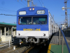
biggulz Posted November 12, 2011 Share Posted November 12, 2011 Hi All - I recently purchased the Kato 10-922 Series 205-3100 Senseki Line Mangattan Liner II (4-Car Set) from Plaza Japan. Since then I have been researching the site for DCC conversion.My current thinking is to proceed with the Digitrax Zephyr starter set (unless anyone sees a benefit to purchasing the Kato version). I am pretty confident I understand the motor car decoder install so I will most likely use the DZ125 decoder. For the cab cars i have a few questions. I am thinking i should go with the TCS FL4 (or the DF11r3 if i can get it) due to leaving the bulbs alone (unless someone gives me better advice) Can anyone guide me on exactly how I should wire up the cab car? Do I just solder wires to the light board? Ok, so here are some pictures below that show the cab car dis-assembled as well as the light fixture. It would be helpful to me to know which color wires go where so I don't do anything wrong starting out. Thanks much for any help I can get. Pete Link to comment
nik_n_dad Posted November 12, 2011 Share Posted November 12, 2011 I just had this one converted by my LHS, that really doesn't do anything with Japanese trains, but apparently it was a very simple conversion. If the shells are easy to pop off I'll try to take some pictures next week. We did use the FL4's (2) for the cab cars and the M1 for the motor car. This combination (thank to Captain O) has been a great combo for EMUs. I'd steer away from the z-scale decoders; I've had mixed results. I'd probably also swap out the bulbs for LEDs. Link to comment
CaptOblivious Posted November 12, 2011 Share Posted November 12, 2011 Don't forget that the bulbs need to be isolated from the rails just like the motor does. Bulb conversions are often a little easier because you can isolate one side simply by removing the diodes (which will need to go anyway). Search through the for a here, and my website (http://akihabara.artificial-science.org) for write ups on how to do Kato cab car conversions. Link to comment
The_Ghan Posted November 12, 2011 Share Posted November 12, 2011 Cap'n, You don't replace the bulbs with LED? bigguls, if you want marked up versions of your photos for LED let me know. I can't do it today, but can one night through the week. Cheers The_Ghan Link to comment
mrpig Posted November 12, 2011 Share Posted November 12, 2011 biggulz - You're light board has led's not bulbs, so one of them will have to be desoldered, flipped and then resoldered. before we can give you info on where to make cuts in the tracks, you will need to decide where you are going to get power for the decoder, ie. are you going to power the decoder from the lightboard, or solder it's power wires directly to the long brass pickup strips. Sometimes where you mount the decoder influences where you power it from. If you take power from the lightboard there will be more cuts. If you take power from the pickup strips, there will be less cuts but you must ensure the lightboard is insulated from the strips. Also, you need to decide which of the 2 decoders you are going to use as the installation will be quite different. If you can get the one from ngdcc, it will be a very simple install as it is bi-polar. Only 4 wires, a little insulating and no cutting tracks on the board. Link to comment
CaptOblivious Posted November 12, 2011 Share Posted November 12, 2011 Cap'n, You don't replace the bulbs with LED? Not always, no. Especially if the bulbs look good as is! Makes the conversion simpler, usually. For example, the Kato Super Hitachi uses bulbs on flexible leads; installing the lightboard into the retainer requires you to slot the bulbs into two just-big-enough holes, which requires the leads be flexible. Finding LEDs to fit into the holes, and finding a way to permit a bit of give in the soldering so it can be reassembled proved impossible. Much easier to leave the bulbs intact! Link to comment
KenS Posted November 12, 2011 Share Posted November 12, 2011 My current thinking is to proceed with the Digitrax Zephyr starter set (unless anyone sees a benefit to purchasing the Kato version). First, no matter what you use for decoders on the train, you can use anyone's DCC command station, it doesn't need to be a Digitrax/Kato system. There are other threads here comparing the various alternatives you should probably check out. Second, the Kato D101 is Digitrax's original DCS50 Zephyr, with some Japanese text on the front, and possibly Kato-compatible connectors rather than screw terminals on the back, but I haven't seen a photo that confirms that. The DCS50 is a solid system (I have the Digitrax version). But for the cost of the D101, you could buy Digitrax's new Zephyr Xtra (DCS51) at list (and they're usually sold for less), which can hold more trains in memory and has extra function buttons (for sound). Neither of these is necessary in a starter system, and extra function controls can be had by adding a DT400 hand-held throttle (which costs about as much as the Zephyr) which you're going to need anyway if the "more than ten trains in memory" part matters. You can run more than 10 trains (sequentially) on either, as storing the number is just a convenience if the train isn't running. But if you're going to spend the money, why not get the extra features? It's possible Kato will come out with their own version of the DCS51. Likely, even, as Digitrax appears to have discontinued the DCS50, so eventually the inventory of boards will run out. But there's been no word on one yet. But I don't see any real benefit in a Kato-branded command station. And if you shop around, you might be able to find an old Zephyr on clearance for a lot less. Just make sure it includes the wall-wart power supply. They're sold without them as well as with them (for people who want to provide their own power supply). Link to comment
Dani Posted November 12, 2011 Share Posted November 12, 2011 Hi, I have the same train, and I'm also converting it to DCC and installing interior lighting. I just posted the motor car DCC conversion in my blog, no time for more That's the post, may be it can also help you: http://clubncaldes.blogspot.com/2011/05/kato-10-922-mangattan-interior-lights.html But the post from Akihabara Station will be surely much better, it's a must read article. I hadn't time to write about Mangattan cab car, but I think it's similar to Kato 10-351: http://clubncaldes.blogspot.com/2011/11/kato-10-352-181-series-digitalization.html My solution usually is to take out one of the led, turn it, and solder just the common leg (positive or negative depending the decoder common wire). Then you solder the common wire from decoder and each output to each led. It's like that unless you use a decoder capable to switch the polarity of the auxiliary output, but that's not the case of FL4 and most of decoders. I also used FL4 for a cab car, and I think it's not a good idea. Lights are not direction dependent! Cheers, Dani. Link to comment
The_Ghan Posted November 13, 2011 Share Posted November 13, 2011 Since my wife forgot to fully schedule my weekend for me I was able to review your cab car lighting configuration. As Dani says, it is an LED kit. The resistor circled in pink gives that away. It is sized to accept up to 12vDC – it’s a 560 Ohm 1% metal film resistor. That resistor, to me, looks like it is in parallel with the forward lighting LED. Perhaps I don’t understand the circuit or the photo isn’t clear but the current passing through each LED needs to pass through the resistor in series. At any rate the following steps WILL work: 1. Cut where I’ve shown the short pink lines. 2. Remove the resistor. 3. Solder the 5 coloured wires as shown. 4. Solder a 560 Ohm resistor where I’ve shown in green, this is presuming all the stuff under the orange line is connected together. Note: don’t connect an orange wire here. 5. If you are using a motor decoder like the Digitrax DZ125 you need to solder a 1k Ohm resistor between the grey and orange wires and insulate it with a bit of electrical tape or shrink tube. 6. Configure and test the decoder in isolation before installing it. I use alligator clips connected to the track and the two tabs that the red and black wires are soldered to. It doesn’t matter which goes where because the current is AC. When the LEDs are installed correctly only ONE will work at a time, depending on the direction. But as Dani says, one of the LEDs won’t work. Try going forward and going in reverse. Stick a piece of tape on the LED that works, de-solder the other and reinstall it backwards. Test again. They should both work one at a time, depending on the direction of travel. If the wrong ones are working, eg: reverse lights when going forwards, you can change the decoder CV29 with Digitrax to control the normal direction of travel. Alteratively, you can swap the white and yellow wires on the light board. I hope this helps. As I said, this is just one way, depending on where you want to cut and how you want to wire. Cheers The_Ghan Link to comment
The_Ghan Posted November 13, 2011 Share Posted November 13, 2011 BTW, I need someone to teach me how to upload images properly with the small previews. Someone please point me in the right direction. Cheers The_Ghan Link to comment
biggulz Posted November 13, 2011 Author Share Posted November 13, 2011 Thank you for the feedback on this topic. I am still leaning toward the Digitrax DCS51s/Zephyr Xtras since its an inexpensive starter set and can get me into the DCC world for my little two train set up. I am seeing these on ebay for less that $200 so thats good for a starter set. I haven't seen any other starter sets to get me started inexpensively. Ok so I wasn't sure if those were LEDs or not so that's good. I have placed an order with Mr Shuhei Nagasue (NGDCC) for 4 DF11r3a's for the cab cars -- 2 for the Mangattan set I posted and 2 for the Kato 10-911 JR 103 Series (Senseki Line) which looks like it will be more difficult since they look like bulbs (see the pics below...tried to get the board out but was unsuccessful) Ordered the 10-911 from Popondetta and received it in 2 days....great service. I liked mrpig saying it will be a simple install for the Mangattan ... my order from NGDCC should be here in a few days! I am still on the fence with the motor decoder. I like the transponder feature if that will allow me to program in routine stops around the track. I wasn't quite sure about this feature providing me that capability. So I am still leaning toward the DZ125. I like the fact that I can return it if I blow it up and I will be doing my first decoder solder with the motor cars thanks to the great posting by Dani....with pictures! My other choice would be the Lenz Silver mini if that will allow me to program the stops. I was curious .... does anyone know how the Kato FR11 works? I have the Kato 11-210 sets already installed so I wasn't sure if the FR11 works with, or in place of, the light board. Anyone have experience with the FR11? Thanks again for the support on this. Link to comment
bill937ca Posted November 13, 2011 Share Posted November 13, 2011 BTW, I need someone to teach me how to upload images properly with the small previews. Someone please point me in the right direction. Sure can! When you click on quote or reply, maroon text Additional Options... appears just below the text box. Once you click on that text additional options appear, including an Attach box and a Browse button. Once your first attachment is completed, more attachments text will appear beside the current Browse box allowing another photo to be up loaded. Link to comment
The_Ghan Posted November 13, 2011 Share Posted November 13, 2011 Test image attached, but it doesn't appear in the preview. Link to comment
The_Ghan Posted November 13, 2011 Share Posted November 13, 2011 Thanks Bill. Cheers The_Ghan Link to comment
Dani Posted November 13, 2011 Share Posted November 13, 2011 I try to explain better my solution with photos (thanks Ghan for the idea), may be it's better than my English... I think this led circuit is exactly the same than the one I converted, assuming you will be using a decoder with a blue wire (common possitive for lights), and white and yellow (one for each led). In this way you will not need to make cuts in the circuit tracks. I don't see clearly the photos, but seems positive leg of one led is soldered with negative of the other led, and also the opposite. I would un-solder one of the leds and solder it again changing the leg positions, so both positive legs are after the resistance. May be it would be better to change the resistance as Ghan said, but mine works perfect. Cheers, Dani. Link to comment
nik_n_dad Posted November 13, 2011 Share Posted November 13, 2011 I also used FL4 for a cab car, and I think it's not a good idea. Lights are not direction dependent! OK, to program the TCS FL2 or FL4 to have directional headlights, here's how to do it. First, notice that we'll be using the Green and Purple function leads (mapped by default to F1 and F2 respectively; function-only decoders don't come with White and Yellow function leads). Suppose that the Green (F1) is wired to the headlights, and the Purple (F2) to the taillights. To make the headlights (Green/F1) come on when the train is moving forward: CV51 = 0 And the taillights (Purple/F2) come on in reverse: CV52 = 16 For the car at the other end, just reverse those values. Source: http://www.tcsdcc.com/pdf/Advanced%20X%20Features%20v1.pdf TCS tries to be helpful, by organizing programming tasks into tables. Table 11 covers assigning lighting effects to function leads. However, there is no one place to get a complete list of all the tables, and sometimes there are different versions of a table (I count at least two and maybe three versions of Table 11 across various literature). Grr. Can get very confusing. Don figured it out a while back, and it's pretty slick. My LHS didn't think you could do directional lighting either, but I printed Don's write-up for them, now it's SOP. 1 Link to comment
The_Ghan Posted November 14, 2011 Share Posted November 14, 2011 Dani, You need to isolate the two -ve contacts. They're currently connected with solder. Cheers The_Ghan Link to comment
Dani Posted November 14, 2011 Share Posted November 14, 2011 You need to isolate the two -ve contacts. They're currently connected with solder. I don't see it Ghan... I draw what seems to be soldered together in the attached picture, and it make sense in order to command two led by switching polarity. I only see the necessity to isolate (adding tape or cutting directly) the legs shown with the arrow, but I'm not sure if you are referencing those as "-ve contacts". Thanks, Dani Link to comment
The_Ghan Posted November 14, 2011 Share Posted November 14, 2011 Hi Dani, I don't get it. Why won't both LEDs come on at the same time? Cheers The_Ghan Link to comment
biggulz Posted November 14, 2011 Author Share Posted November 14, 2011 I need some clarification here. The decoder I am installing will be the NGDCC DF11r3 with only two wires to attach to the Mangattan light board. As mrpig pointed out "....it will be a very simple install as it is bi-polar. Only 4 wires, a little insulating and no cutting tracks on the board." Can someone help me out with where the attach points would be for the 4 wires and where the insulating would occur. Thanks much for the help here. Link to comment
Dani Posted November 14, 2011 Share Posted November 14, 2011 Ghan: Each positive leg of one led is soldered together with negative leg of the other led. That's how only one led is lit on at the same time, and changing polarity (as in DC) changes the illuminated led. Biggulz: With this polarity changing capable decoder you have to do almost nothing!! That's the easiest way I see to install it: - Isolate this circuit from the metal strips that pick up current from the wheels (with a piece of insulating tape). - Solder white wire to one of the legs and yellow to the other (those legs of the circuit I remarked with an arrow in my last picture of the previous post). - Solder black and red wires to any point of the metal strips taking current from the wheels to feed decoder. Remember black wire goes to the left wheels and red wire to right wheels. If led are not illuminated in correct direction of travel, change white and yellow wire (well, test it before soldering better... ) Cheers, Dani Link to comment
Dani Posted November 15, 2011 Share Posted November 15, 2011 As the image was not clear, yesterday I opened my Mangattan Liner cab car to see it. The circuit is as I expected. Just to confirm it and avoid confusions! Cheers, Dani Link to comment
mrpig Posted November 15, 2011 Share Posted November 15, 2011 Biggulz - Do it just like Dani said above. I have not used the df11r3, but from the info on their website, it is just like the old Lenz LF101XF. I have done about a dozen of those. Really coudln't be any easier, just make sure the lightboard contacts are completely insulated from the pickup strips. Now if only someone would make these in a FL4 sized package. Link to comment
The_Ghan Posted November 16, 2011 Share Posted November 16, 2011 Yuh, The're big decoders. Cheers The_Ghan Link to comment
biggulz Posted November 17, 2011 Author Share Posted November 17, 2011 Thank you again for all your help and support. Easy is the equation I was looking for.... I am going to wire up the second train I mentioned the same way and see what happens. I should have everything delivered by this weekend. As I mentioned before I don't have a large setup....basically the M1 and the V6 outside track i will wire together into the controller so both loops will be active. Then I can grow from there. Link to comment
Recommended Posts
Create an account or sign in to comment
You need to be a member in order to leave a comment
Create an account
Sign up for a new account in our community. It's easy!
Register a new accountSign in
Already have an account? Sign in here.
Sign In Now