All Activity
- Past hour
-
This is might old 😮 But the usual practice should apply. First remove the shell (I expect it should be simply clipped to the chassis) and then figure out how to get to the motor, unclip the bogies and open them. Sorry if I can't get more helpful, I never had such an old Japanese model in my hands. If you don't have one, you should get a fiberglass pen to clean those wheels.
- 1 reply
-
- 1
-

-
I think a lot of the people that would be interested in these wouldn't mind a little gluing / soldering to get custom length ones, so the option to have various length middle sections would be a nice addition. It would probably be worth giving the etched wires a try if they're not a lot of work. If they sell well, you can easily get more of them etched. And if not, it's not a lot of wasted time. Personally I'm more in the camp of wanting to have wires if I have the masts as well. Just the masts always looks a bit off to me, even if to-scale wire would be pretty much invisible. Having wires is of course also a terrible pain when you need to clean the track 🙂 I have built my own catenary from scratch before (fully functional actually, for Euro locos with working pantographs), and there I made a quick jig for the wire, and just soldered together some copper wire. It was rather fiddly, but very doable for the simple type of wire. The 2nd wire you posted would of course be quite a bit more work to scratch build.
- Today
-
Hello, During my récent trip to Japan, I found an EF 65 by Kato at a local market for 500 yen. It'll be fine as a static display piece, but if I can get it running it would be even better! I'm not familiar with this type of motor with two driven bogies, and am wondering how to disassemble and clean everything. Any tips? Thanks in advance, /Philip

-
2025 SL Yamaguchi Schedule Posted
Mutro replied to Mutro's topic in Travel: Tips, Planning & Memories
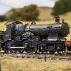
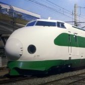
SL Yamaguchi Trip Report 6 We crossed from Kyushu to Honshu via a pedestrian tunnel under the Straights of Kammon yesterday. This tunnel, which connects the cities of Shimonoseki and Mojiko, is bored under the sea just north of the Shinkansen tunnel and is accessed by 180’ deep elevators on each ends. Unfortunately, my friend dropped his iPhone as we entered the elevator and it slipped through the crack, dropping all the way down the 180’ shaft 🥺… But I digress. JR Mojiko Station Mojiko station is a Government Designated Important Cultural Asset, opened on February 1, 1914. The 2-story building constructed in the Renaissance style with high historical valuable is one of the oldest station buildings in Kyushu Kitakyushu Railway History Museum Nearby is the Kitakyushu Railway History Museum, a great find for any railway enthusiast. It’s small but a real gem, showcasing several restored locomotives and railroad memorabilia. There are a couple of nice model railroad layouts in N and HO as well as a well-stocked omiyage / railway nicknack store. Following descriptions by the museum Japanese National Railways No. 59634 First year of manufacture1922 Production company etc.Kawasaki Shipyard The 9600 type was the first domestically produced freight locomotive, and 770 were made. It was used throughout Kyushu and was affectionately nicknamed Kyuroku. Its distinctive feature was the high car body height, due to the boiler being located above the driving wheels. This locomotive was transferred from the Yonesaka Line to the Gotoji Locomotive Depot in 1974. Fans called this locomotive, which had come all the way from afar, "Thank you for your hard work," because of its number. It worked in the Chikuho region for less than a year, but it was one of the last steam locomotives in the Kitakyushu region. Japanese National Railway C59 No. 1 First year of manufacture1941 It was born as the main locomotive on the Tokaido and Sanyo main lines. It was assigned to Moji in 1956 and used for the sleeper express "Asakaze" and the express "Unzen", and in 1962 it was transferred to Kumamoto. It also pulled Kumamoto's first express "Mizuho", which was launched that same year. When the electrification of Kumamoto was completed in 1965, it was scrapped as it had no other place to be transferred to due to its heavy axle load for main line use. Nine cars of the same model were dismantled, but this car was kept on display at Kokura Factory as a quasi-railway monument. It had traveled the equivalent of 62 times around the earth before being scrapped. Japanese National Railways Kuha 481 No. 603 First year of manufacture1969 Production company etc.Nippon Sharyo The 481 series, which can run on both AC and DC, is an advanced version of the electric express "Kodama" that appeared in 1958, and was born in conjunction with the electrification of Kumamoto. This car was born in 1969 as Kuro 481-5 and was active in the Tohoku region, but in 1983 it was assigned to the Kagoshima Depot, where it was converted into a regular seating car and its car number changed to Kuha 481-603. After being used as the express "Nichirin", "Kamome" and "Ariake" in Kyushu, it has been preserved at the Kokura Factory since 1997. Japanese National Railways ED72 No. 1 First year of manufacture1961 Production company etc.Toshiba It was introduced as an AC electric locomotive for use in the Kitakyushu electrification project. Since it had a heating boiler, it was characterized by its long car length and the presence of a middle bogie in the center where no power was transmitted. As heating was changed from steam to electricity and the boiler became unnecessary, it was no longer necessary to limit it to passenger use, and in its later years it was also used for freight trains. This vehicle was a prototype locomotive and is slightly different in style from other locomotives of the same type, but it was preserved at Oimatsu Park in Moji Ward, Kitakyushu City as Kyushu's first AC electric locomotive. Japanese National Railways Kiha 07 No. 41 First year of manufacture1937 Production company etc.Nippon Sharyo This is a typical pre-war mechanical (clutch-driven gear change) diesel railcar, and when the cars were coupled together, the drivers on both sides would signal to each other as they drove. In 1952, the gasoline engine was changed to a diesel engine. This car was allocated to Bungomori Locomotive Depot in 1957 and used on the Miyahara Line. It was retired in 1969 and was carefully stored at Bungomori Locomotive Depot and Oita Depot. This is the only car of its type manufactured before the war that has retained its original form. Japanese National Railways EF10 No. 35 First year of manufacture1941 Production company etc.Toshiba When the Kanmon Tunnel was opened in 1942, this section became the only electrified section, and an EF10-type DC electric locomotive was deployed specifically for the tunnel, with the locomotives being replaced at Shimonoseki and Moji. In 1961, the Kyushu side was electrified with 20,000 volts AC, and the Honshu side with 1,500 volts DC, and the role was handed over to dual-purpose locomotives. This locomotive was then used in various parts of Honshu until 1979, and after its retirement it was preserved in Moji Osato Park. Japanese National Railways Kuhane 581 No. 8 First year of manufacture1967 Production company etc.Hitachi, Ltd. It debuted as the world's first sleeper train express "Gekko". It is a convenient express train that can operate both day and night as a seated express train during the day. In 1970, the number of trains increased and it was used for express trains between Kansai and Kyushu, such as "Tsubame" and "Hato". In 1984, it was converted into a local train at Kokura Factory and reborn as the AC train 715 series (Kuha 7151), and was mainly used on the Nagasaki and Sasebo lines until 2000. After being scrapped, it was repainted in the express train livery it had when it was first introduced and was preserved at Kokura Factory. Series 14 Sleeper Car First year of manufacture1972 Production company etc.Nippon Vehicles The 14 Series 11 sleeper express train was manufactured by Nippon Sharyo in 1972 as the second generation sleeper express train. It began operation as a replacement for the 20 Series "Sakura" and "Mizuho". The preserved "Suhanef 14 Series 11" has a diesel engine under the floor, and can send electricity to five cars including the train itself. When it was manufactured, it was a three-tiered sleeper with a conductor's room, but in 1982, the sleepers were remodeled to two tiers. It was in service for a long time, but the sleeper express "Mizuho" was discontinued in 1994, the "Sakura" in 2005, and the "Fuji" and "Hayabusa" in 2009, and this was the last operation, but it was in service as a special train in Kyushu until 2010, and was preserved at the Kumamoto Vehicle Center after its retirement.
- 20 replies
-
- 1
-

-
- sl
- sl yamaguchi
- (and 6 more)
-

Bill's Excellent Swiss Adventure
chadbag replied to bill937ca's topic in Travel: Tips, Planning & Memories
The one time I was in Basel I took a French train so ended up at the Basel SBB Bh. I was in Offenburg for a few hours and then took a train to Strasbourg / Straßburg and took the train from Strasbourg to Basel where I spent a few hours and then a train to Bern (actually Zollikofen). That's because that was my actual destination where I had a bed waiting and an early morning appointment the next day. This was all 35 years ago. So it was all loco hauled normal wagons back then. I'd love to go ride the rails in Switzerland and visit the various places. I've been in Zürich and/or Bern a few times but it was all back in the early 90s. I've gotten a bunch of late model Swiss locomotives plus the RhB stuff from KATO as well. So I need to go see the real ones. I'd like some of the IC/IR stuff but Euro models have gotten so €€€€ Thanks for the pics Bill -
Tony, with block wiring every block of track on the layout is controlled by a DPDT switch that switches the power to that block from cab A or B or off. Doesnt matter where the track block is on the layout, if it’s on the inside or outside loop, or in a siding or yard or which control panels the DPDT is on. Its simply all blocks are the same in their wiring with the track power feeds going to a DPDT that is connected to cab A and cab B to choose from. I think the cleanest option is to just split the control panels into two, one for the Upper side of the layout and the other for the Lower side of the layout. Basically the same block pattern as before but just split the end 180 curve blocks on each end into two 90 degree halves so one 90 can go into the upper and one into the lower control panel [yellow line shows the division of the upper and lower sides of the layout}. This lets you do full operations of the yard and sidings of each side easily. When you want to run trains around the two loop mainlines you will just have to set those mainline blocks to the desired cab on the appropriate block DPDTs on both of the control panels. But this is a lot easier than one mega control panel that your ill have to operate half the layout over your shoulder sort of in reverse, have a large and very deep control panel to have the full layout on it, and be a lot of wires in one control panel. Remember each red dot is a pair of insulated unijoiners to isolate both rails of each block. The green dots are power drops for each block [some blocks need more than one power drops due to length and/or crossovers and switches] with each dot having wires to each rail that then wires back to the center of its DPDT. All the blocks are wired the exactly the same no matter where they are on the layout on the inner loop, outer loop, siding or yard. cheers jeff
-
Bill's Excellent Swiss Adventure
bill937ca replied to bill937ca's topic in Travel: Tips, Planning & Memories
On the return trip from Basel I took the IR37 which was simply the first train I encoutered heading for Zurich. It takes a different route than the IR36 and the travel time is comparable. Photos are on arrival at Zurich and inside the lower level coach.
-
Jeff Just one quick point question, as im looking at two control panels one either side of the layout, lets say cab A on the left and cab B on the right but yes wired together as you have shown, can i wire DPDT switches to cab A for that side of the layout keeping to the wiring instructions as we have discussed, but also do the same wiring DPDT switches to cab B for that side of the layout, so in fact we have a control panel and control in front or near each station or yard What im asking is for cab control to work do all the DPDT switches for block control have to be on the one power control Tony
-
Bill's Excellent Swiss Adventure
bill937ca replied to bill937ca's topic in Travel: Tips, Planning & Memories
Now the S-Bahn network. There are 32 lines in the Zurich S-Bahn network. Of those 32 lines 31 run through Zuirch's main station. The S-Bahn will get you to work, take you to or from the airport. All services operate every 30 minutes with some lines doubling up for 15 minute frequencies. There is also the Forchbahn interurban lines S18 which is part of the S-Bahn network. https://en.wikipedia.org/wiki/Zurich_S-Bahn These trains in the photos are RABe 514 double deck commuter sets. There are 74 first class seats, 304 second class seats in a 100 meter four-car train. These sets are frequently doubled up. S-Bahn sets are red and white with blue roofs. The lower level of one of cars of each set has a very generous provision for baby carriages and bicycles. https://en.wikipedia.org/wiki/SBB_RABe_514 The photos were taken at Zürich Tiefenbrunnen, Bahnhof at the south end of the VBZ tram and trolleybus network on the east shore of Lake Zurich.
-
Here is his video about his stay at a hotel in Ozu: https://www.youtube.com/watch?v=2ldQtkiYBCk Ciao, Tony
-
I will read it a few times hehehe cheers Jeff I have printed out your diagrams i only have black and white lol so im using pens to color them know it actually helps a little to picture the wiring as im doing it Tony
-
Tony, for the lift out bridge you just need to jump the power for each of the two tracks that go thru it to the block rest of in the adjacent module. I would not bother to try to do two sets of connections on both sides of the pull out module. Wire that last bit of the module then with another feed from around the other side of the layout. I diagrammed the power feed to those two blocks [one on inside loop and one on outside loop] long that is the end curve and across the pull out module and into the yard. You can run one wire around one side of the layout to get the curve and a jumper to the pullout section and the rest of the block on the other side of the pullout can get ged from another feed from the other side of the layout [you could reverse this if the lift out is already wired to jump on the yard side]. The blue is the power feeds going to outside loop block and the red is the power feed wires going to the inside loop block. Control panel could be anywhere just the example that for these two blocks you have to do power feeds coming from two sides if you have a single power connection between the pull out module and one of the adjacent modules. make sense? jeff
-
cheers Jeff Yes i was worried about bugging you but its becoming clearer so im hoping i will be out of your hair soon, except for the turnout wiring lol ( LATER ) Did you see how i wired the lift out bridge section ?? i was assuming i had a bus wire running to and from this section so i am now wondering if i have this wiring correct, i was going to plug it in either end connecting to a bus wire ?? i am now assuming it will be connected via a dropper wire in a block section, i will keep looking at it any way cheers again Jeff i have printed all this out and will try drawing it up and think hard and concentrate on it for a while Cheers Tony
-
Tony, no worries at all. Doesnt take much time at all and happy this is helping you figure it all out and get er done! Diagram scribbles only take a minute or two, but I shouldn’t have been watching tv while i responded as i flipped those wires! when you go to wiring all this up its mainly a matter of making sure you get all the polarities right with the throttles and the block power feeds on the DPDT switches. Throttles are pretty easy just do like throttle A to the top of all the switches and throttle b to the bottom of all the switches and just make sure to keep like black on the left and red on the right. for the polarity on the power feeds from the blocks/tracks you want to be consistent and like black to the outer rails and red to the inner rails [or visa versa]. For sidings you can trace which is the inner rail [ie the inside rail of each big loop] from it branching off of the mainline loop and same then with the outside. If you screw up at some point on one you can always just reverse the wires at teh terminal block at the control panel for that block. same goes for blocks that may have multiple power drops just want to keep all those wired with the same color to each rail and not mix them or you will get a short. We can talk later about how to use your multimeter later to help test tings before you turn on power to each block to make sure its working correctly. having the little terminal block at each power drop just makes life easy. Make all your soldered track feeds wtith like 25cm of wire and that will get you to under the layout and to the terminal block. Then you can measure out the long power feed wire going all the way back to the control panel to the terminal block there. This way you dont have to try to make one piece of wire to go from track folder joint to dpdt and you can do each step around the layout easily in phases. to connect all the power feeds from the throttles to the dpdt you can just wire multiple feeds from the dpdt to a terminal and then back to one lead to the throttle. If you need to do multiple ones of these just use little jumper wires to multiple terminals from your one throttle power feed. Basically you make one of these for each throttle to make your power feeds to each end of the DPDTs from each throttle. Dressing all your wiring in the control panel is going to be a challenge and not have it a total bowl of spaghetti. You may want to just take a few DPDTs and add like 25cm of wire on all the terminals and mount the switches in a hunk of cardboard and mess which how best to dress the wires cleanly in the space. The wiring can be a limiting factor in how small you can make the control panel. Don’t just set a control panel size without getting an idea of how much the wiring takes up in space and being able to trace wires well. You might also get different colors for the power feeds from each of the throttles to the DPDT switches as well to help you easily see which is throttle A feed, throttle B feed, and block feed inside the control panel. The whole run from track to the DPDT for a block can just be the standard two strand Red/Black wire you have. Then see if you can find some different colors like blue/white and green/yellow to use for the throttle power feeds. You could do the throttle power feeds as individual wires if getting colored paired wire is hard. If you want to neaten each pair to a switch up then a couple little rings of heat shrink can help keep the wires together but allow it to move well. Using a larger piece of heat shrink to hold two wires together will greatly reduce its flexibility but short little chunks will do well. Since all the throttles feeds are essentially the same you can just grab one of each color and bundle the two with a few little rings of heat shrink to keep them together to the DPDT switches. Trying to use double stranded for the throttle fees may be tough splitting the back far enought o be manageable. Keep asking questions as things come up, no worries on bugging me. Glad its all coming in focus for you. Cheers, jeff
-
KATO C30-7 CORELESS MOTOR ok, finally figured out which glue works to hold 1mm shafts to 1mm adapters. G13 some kind of rubber cement. Stuper glue and white glue did not hold despite having roughed up the shafts. Anyway, C30-7 running at 1 volt now. Ammeter doesn't move at all, no capacitor needed. Totally repeatable process, so am now looking at some of my older Kato stuff.
- Yesterday
-
cheers Jeff, yes this must be sinking in ive just picked up on the reversed polarity Thank you for clearing up the bus wire question for me yes this is all a lot clearer, i will spend some time doing a comprehensive diagram and leave you in peace again, im sorry i will be back to get your ok once you've looked it over Thank you for spending your time on me again Cheers Jeff Tony
-
Yeah a lot of the time I’m putting trains out at shows and funky lighting, in a hurry, and my close eye site is not as good as it use to be so i went to the stickers to cheat. Jeff
-
Tony, fixed the third graphic i had reversed a polarity jeff
-
Tony, Yes using a buss wire for the inner and one for the outer is how you would wire the layout for point power control, wiring the mainline for each loop to its buss and then control of the power to sidings off the loops is controlled by how the points are set. for block wiring you just have a power lead from the control panel to each of your track blocks. This power lead goes from your power drop on the track for that block back to the DPDT switch on the control panel. This should be 18g wire as you will have some running a long distance and better to have a bit beefier wire for power transmission over a distance. If you have a block with a longer piece of track you may end up doing 2 or 3 power drops from the track within the block that all connect to that block’s power feed from the control panel dpdt that feeds it power from one or the other throttles. Here is the basic wiring for each block on the layout Power drops from the track on each block [this may be more than one]. These are the 20 or 18g soldered wire drops from the underside of the tracks. These leads only need to be about 12” long. connects to one side of a 2 pole terminal block under the layout. You can just cut those 12 block terminal blocks into six 2 pole terminal blocks. other side of the terminal blocks you connect your main power feed wire [best 18g] that runs all the way back to just outside or inside of your control panel. at the control panel you can mount 12 pole terminal blocks and connect your pair of power feed wires to 2 terminals on the other side of that terminal connect a short piece of 18g wire that runs into the control panel to its DPDT switch at the DPDT switch you solder on the end of the short wire to the center poles of your DPDT switch. Throttle A and B are wired to the top and bottom pairs of terminals of the DPDT switch. This just requires wiring a bunch of short pairs of wires from one spot on the control panel that all connect together at one end and that is attached to the throttle lead. The other ends go to top pair of terminals on each DPDT switch. Then repeat with a bunch of wires from throttle B to the bottom pair of terminals on the DPDT switch Here is a diagram from track to throttle with the terminal strips in there Here is the diagram for wiring a long block track with multiple feeders here is the wiring of a couple of dpdts in the control panel.
-
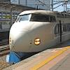
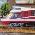
Thanks 200 I will whip out the magnifyer and take a closer look at the cars and number then according to the included instructions. I hope the set comes with the sticky numbers to put on the bottom of the cars lol. I appreciate you replying to my question.
-
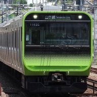
If you take a closer look at your model, you'll find the car number annotation on the right side of the car, next to the 4th (aft, as seen from the 1st car), just above the priority seat/wheelchair access pictograms and below the upper yellow band. Connect them all from 1 to 10, just make sure to keep the car number annotations and pictograms on the right side of all the cars (as seen from car no.1), and you got the prototypical formation, easy peasy...
-
Jeff have i done away with running a 18G bus wire around my layout under each track inner and outer using the block cab method ?? or am i still connecting my cab control dropper wires to the bus wire somehow ?? I hope im explaining correctly Tony
-
I have added a few signs to the current pack that could be attached to posts. The theme of the pack is warning signs so these are linked to construction and general works. I will work on other advertising on future downloads. It would be great to send you some samples. I have ordered 5 copies of a test sheet so I will have 4 to send out for testing and feedback. The repeating pattern does make to quite straightforward for extending. Like you say it would be challenging to actually align and glue. The idea I had to make that easier may or may not work, I won't know until the etch arrives and can be tested. It looks like this: It is a little complex but so is the prototype. The main truss (middle) folds up to give the basic shape. Then there is a top and bottom rail to add on both sides, these fold to from L beams with the brackets to attach to the legs attached. There are little slots along the L beams to locate over small tabs on the main truss to align everything correctly. The main beam takes up a lot of space on an etch however the L beams fit in much smaller spaces. I thought I could make an adjustable version with different length L beams and the main truss split into two halves. Then I could offer different length middle sections to vary the span. Essentially you would attach the outer sections of the main truss to the upper L beam using the tabs to locate it accurately. Then depending on which length L beam you select there would be a middle truss that folds up and drops into the gap. then the lower L beams can be slotted on the secure everything in place and hide the joins. They really aren't my thing as they need to be slightly over scaled to work. I think have no wires looks better however I know some people like to see the wires. There are some etched wires out there, Cityscape Studios recently used some on his Tokyo Station diorama. It is good point that there are lots of different lengths that would be needed. The advantage is they are so simple only takes a few minutes to draw them up so I would be willing to give it a go. I could design in an optional attachment point on the catenary to hold them in place. Joe
-
Thanks Bill I did exactly that and went to the Kato website and found the instruction manual for my set thanks.
-
Ahh bummer! Yes thats the issue now on getting customs forms filled out correctly by vendors. For US customs these have also changed. They also want the HTS number. One of your club member just had an order go over a little bit on $800 and owed a couple of bucks in duty but then ups did $40 or so in fees as the over $800 required full customs process and thus the big fees. Hopefully vendors will figure out how to make this as smooth as possible in the new worlds order for us customs. jeff