All Activity
- Today
-
I will read it a few times hehehe cheers Jeff I have printed out your diagrams i only have black and white lol so im using pens to color them know it actually helps a little to picture the wiring as im doing it Tony
-
Tony, for the lift out bridge you just need to jump the power for each of the two tracks that go thru it to the block rest of in the adjacent module. I would not bother to try to do two sets of connections on both sides of the pull out module. Wire that last bit of the module then with another feed from around the other side of the layout. I diagrammed the power feed to those two blocks [one on inside loop and one on outside loop] long that is the end curve and across the pull out module and into the yard. You can run one wire around one side of the layout to get the curve and a jumper to the pullout section and the rest of the block on the other side of the pullout can get ged from another feed from the other side of the layout [you could reverse this if the lift out is already wired to jump on the yard side]. The blue is the power feeds going to outside loop block and the red is the power feed wires going to the inside loop block. Control panel could be anywhere just the example that for these two blocks you have to do power feeds coming from two sides if you have a single power connection between the pull out module and one of the adjacent modules. make sense? jeff

-
cheers Jeff Yes i was worried about bugging you but its becoming clearer so im hoping i will be out of your hair soon, except for the turnout wiring lol ( LATER ) Did you see how i wired the lift out bridge section ?? i was assuming i had a bus wire running to and from this section so i am now wondering if i have this wiring correct, i was going to plug it in either end connecting to a bus wire ?? i am now assuming it will be connected via a dropper wire in a block section, i will keep looking at it any way cheers again Jeff i have printed all this out and will try drawing it up and think hard and concentrate on it for a while Cheers Tony
-
Tony, no worries at all. Doesnt take much time at all and happy this is helping you figure it all out and get er done! Diagram scribbles only take a minute or two, but I shouldn’t have been watching tv while i responded as i flipped those wires! when you go to wiring all this up its mainly a matter of making sure you get all the polarities right with the throttles and the block power feeds on the DPDT switches. Throttles are pretty easy just do like throttle A to the top of all the switches and throttle b to the bottom of all the switches and just make sure to keep like black on the left and red on the right. for the polarity on the power feeds from the blocks/tracks you want to be consistent and like black to the outer rails and red to the inner rails [or visa versa]. For sidings you can trace which is the inner rail [ie the inside rail of each big loop] from it branching off of the mainline loop and same then with the outside. If you screw up at some point on one you can always just reverse the wires at teh terminal block at the control panel for that block. same goes for blocks that may have multiple power drops just want to keep all those wired with the same color to each rail and not mix them or you will get a short. We can talk later about how to use your multimeter later to help test tings before you turn on power to each block to make sure its working correctly. having the little terminal block at each power drop just makes life easy. Make all your soldered track feeds wtith like 25cm of wire and that will get you to under the layout and to the terminal block. Then you can measure out the long power feed wire going all the way back to the control panel to the terminal block there. This way you dont have to try to make one piece of wire to go from track folder joint to dpdt and you can do each step around the layout easily in phases. to connect all the power feeds from the throttles to the dpdt you can just wire multiple feeds from the dpdt to a terminal and then back to one lead to the throttle. If you need to do multiple ones of these just use little jumper wires to multiple terminals from your one throttle power feed. Basically you make one of these for each throttle to make your power feeds to each end of the DPDTs from each throttle. Dressing all your wiring in the control panel is going to be a challenge and not have it a total bowl of spaghetti. You may want to just take a few DPDTs and add like 25cm of wire on all the terminals and mount the switches in a hunk of cardboard and mess which how best to dress the wires cleanly in the space. The wiring can be a limiting factor in how small you can make the control panel. Don’t just set a control panel size without getting an idea of how much the wiring takes up in space and being able to trace wires well. You might also get different colors for the power feeds from each of the throttles to the DPDT switches as well to help you easily see which is throttle A feed, throttle B feed, and block feed inside the control panel. The whole run from track to the DPDT for a block can just be the standard two strand Red/Black wire you have. Then see if you can find some different colors like blue/white and green/yellow to use for the throttle power feeds. You could do the throttle power feeds as individual wires if getting colored paired wire is hard. If you want to neaten each pair to a switch up then a couple little rings of heat shrink can help keep the wires together but allow it to move well. Using a larger piece of heat shrink to hold two wires together will greatly reduce its flexibility but short little chunks will do well. Since all the throttles feeds are essentially the same you can just grab one of each color and bundle the two with a few little rings of heat shrink to keep them together to the DPDT switches. Trying to use double stranded for the throttle fees may be tough splitting the back far enought o be manageable. Keep asking questions as things come up, no worries on bugging me. Glad its all coming in focus for you. Cheers, jeff
-
KATO C30-7 CORELESS MOTOR ok, finally figured out which glue works to hold 1mm shafts to 1mm adapters. G13 some kind of rubber cement. Stuper glue and white glue did not hold despite having roughed up the shafts. Anyway, C30-7 running at 1 volt now. Ammeter doesn't move at all, no capacitor needed. Totally repeatable process, so am now looking at some of my older Kato stuff.
- Yesterday
-
cheers Jeff, yes this must be sinking in ive just picked up on the reversed polarity Thank you for clearing up the bus wire question for me yes this is all a lot clearer, i will spend some time doing a comprehensive diagram and leave you in peace again, im sorry i will be back to get your ok once you've looked it over Thank you for spending your time on me again Cheers Jeff Tony
-
Yeah a lot of the time I’m putting trains out at shows and funky lighting, in a hurry, and my close eye site is not as good as it use to be so i went to the stickers to cheat. Jeff
-
Tony, fixed the third graphic i had reversed a polarity jeff
-
Tony, Yes using a buss wire for the inner and one for the outer is how you would wire the layout for point power control, wiring the mainline for each loop to its buss and then control of the power to sidings off the loops is controlled by how the points are set. for block wiring you just have a power lead from the control panel to each of your track blocks. This power lead goes from your power drop on the track for that block back to the DPDT switch on the control panel. This should be 18g wire as you will have some running a long distance and better to have a bit beefier wire for power transmission over a distance. If you have a block with a longer piece of track you may end up doing 2 or 3 power drops from the track within the block that all connect to that block’s power feed from the control panel dpdt that feeds it power from one or the other throttles. Here is the basic wiring for each block on the layout Power drops from the track on each block [this may be more than one]. These are the 20 or 18g soldered wire drops from the underside of the tracks. These leads only need to be about 12” long. connects to one side of a 2 pole terminal block under the layout. You can just cut those 12 block terminal blocks into six 2 pole terminal blocks. other side of the terminal blocks you connect your main power feed wire [best 18g] that runs all the way back to just outside or inside of your control panel. at the control panel you can mount 12 pole terminal blocks and connect your pair of power feed wires to 2 terminals on the other side of that terminal connect a short piece of 18g wire that runs into the control panel to its DPDT switch at the DPDT switch you solder on the end of the short wire to the center poles of your DPDT switch. Throttle A and B are wired to the top and bottom pairs of terminals of the DPDT switch. This just requires wiring a bunch of short pairs of wires from one spot on the control panel that all connect together at one end and that is attached to the throttle lead. The other ends go to top pair of terminals on each DPDT switch. Then repeat with a bunch of wires from throttle B to the bottom pair of terminals on the DPDT switch Here is a diagram from track to throttle with the terminal strips in there Here is the diagram for wiring a long block track with multiple feeders here is the wiring of a couple of dpdts in the control panel.
-
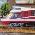
Thanks 200 I will whip out the magnifyer and take a closer look at the cars and number then according to the included instructions. I hope the set comes with the sticky numbers to put on the bottom of the cars lol. I appreciate you replying to my question.
-
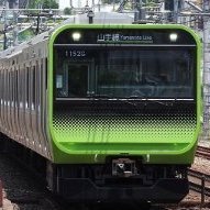
If you take a closer look at your model, you'll find the car number annotation on the right side of the car, next to the 4th (aft, as seen from the 1st car), just above the priority seat/wheelchair access pictograms and below the upper yellow band. Connect them all from 1 to 10, just make sure to keep the car number annotations and pictograms on the right side of all the cars (as seen from car no.1), and you got the prototypical formation, easy peasy...
-
Jeff have i done away with running a 18G bus wire around my layout under each track inner and outer using the block cab method ?? or am i still connecting my cab control dropper wires to the bus wire somehow ?? I hope im explaining correctly Tony
-
I have added a few signs to the current pack that could be attached to posts. The theme of the pack is warning signs so these are linked to construction and general works. I will work on other advertising on future downloads. It would be great to send you some samples. I have ordered 5 copies of a test sheet so I will have 4 to send out for testing and feedback. The repeating pattern does make to quite straightforward for extending. Like you say it would be challenging to actually align and glue. The idea I had to make that easier may or may not work, I won't know until the etch arrives and can be tested. It looks like this: It is a little complex but so is the prototype. The main truss (middle) folds up to give the basic shape. Then there is a top and bottom rail to add on both sides, these fold to from L beams with the brackets to attach to the legs attached. There are little slots along the L beams to locate over small tabs on the main truss to align everything correctly. The main beam takes up a lot of space on an etch however the L beams fit in much smaller spaces. I thought I could make an adjustable version with different length L beams and the main truss split into two halves. Then I could offer different length middle sections to vary the span. Essentially you would attach the outer sections of the main truss to the upper L beam using the tabs to locate it accurately. Then depending on which length L beam you select there would be a middle truss that folds up and drops into the gap. then the lower L beams can be slotted on the secure everything in place and hide the joins. They really aren't my thing as they need to be slightly over scaled to work. I think have no wires looks better however I know some people like to see the wires. There are some etched wires out there, Cityscape Studios recently used some on his Tokyo Station diorama. It is good point that there are lots of different lengths that would be needed. The advantage is they are so simple only takes a few minutes to draw them up so I would be willing to give it a go. I could design in an optional attachment point on the catenary to hold them in place. Joe
-
Thanks Bill I did exactly that and went to the Kato website and found the instruction manual for my set thanks.
-
Ahh bummer! Yes thats the issue now on getting customs forms filled out correctly by vendors. For US customs these have also changed. They also want the HTS number. One of your club member just had an order go over a little bit on $800 and owed a couple of bucks in duty but then ups did $40 or so in fees as the over $800 required full customs process and thus the big fees. Hopefully vendors will figure out how to make this as smooth as possible in the new worlds order for us customs. jeff
-
Check the Hobby Search listing for that info. Probably as a image. Or check the manufacturers site. Again probably as an image showing which car has the motor.
-
I use the dots to tell me which trains have decoders in them or not. I know what you mean when you lose a dot it drove me nuts not knowing what cars had a decoder or not. I'm going to give it a shot and see how it goes. I may take the numbering of trains cars to an extreme or not.
-
7th Annual Parksville Railway Day August 24, 2025
grumbeast replied to RS18U's topic in Club and Show News
I’ll hopefully be there, I’m down in Nanaimo. Were you at the show in a couple of weeks back in Nanaimo? I think I met your group if so. I’d like to be more involved with people close to me- 1 reply
-
- 2
-

-
My music item order ran just over $900 and was only a Japanese product. Part of the problem was that the sender included the shipping cost which inflated the price. If/when I do something like that again, I would make sure that the shipping is charged separately. Tony
-
So was this a japanese made product or a chinese made product? Or was it past de minimis? Yes my fear is this all will lead to fee city for the shippers to gorge on as its usually per shipment charge not a percentage like duty. jeff
-
I used those tiny dots like 3/8” diameter and just found a flat bit on the car to push it onto. Ive lost a few when they sometimes rub on the foam. Ive always meant to go back and figure out a better solution of where to put numbering but I've never gotten to it and im not all that concerned if i screw up now and then or order or orientation, but i do know it pains some a lot. jeff
-
Thanks, Jeff I'll be numbering that set tonight.
-
To follow up on what @Kingmeow noted, my recent package from Plaza Japan did not have extra charges either. I was concerned as the MicroAce box clearly states Made In China. One caution with Fed Ex - I recently had some music items shipped from Japan and while the product was delivered without an issue, I did get a follow up letter from Fed Ex with duty charges. And since these companies like to pile on, about a third of the bill was for their fees. Tony
-
Yes Martjin, dont worry about the server, it works. Family first. jeff
-
Yes instructions usually give you that info on car order. I use to cheat and then just put little round stickers on the bottoms of cars to indicate order and direction [if couplers didnt do that for you.]. You can indicate direction by the orientation of the number on the sticker [ie if you hold the car upside down in front of you then you always rotate the car down on the tracks in a single direction when putting them on the tracks like rotating the roof towards you.] someone in our club put the numbers on the foam insert and was just careful to put them in and out of the case in order, but this was easy to screw up if you got distracted, but then you dint have a little sticker on the bottom of your cars. jeff