beakaboy Posted November 6, 2015 Share Posted November 6, 2015 Hi guys. Hope someone can help me on this. I acquired this loco a couple of years ago along with some other older European locos. photos attached. I forgot to photograph underneath the fuel tank where there are microchips and a circuit board. Can't get any response from loco on DC. Tried programming track on My NCE system and loco buzzed and both headlights came on. Removed very quickly! I like the look of the loco and have held on to it in the hope of getting it operating. Any Help appreciated. John Link to comment
HantuBlauLOL Posted November 6, 2015 Share Posted November 6, 2015 (edited) DC or DCC? Euro model's circuit board is very similar between DC and DCC.. Also any pic of the other side of the circuit board? Edited November 6, 2015 by HantuBlauLOL Link to comment
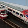
Welshbloke Posted November 6, 2015 Share Posted November 6, 2015 (edited) There's a possibility that this has a Selectrix decoder fitted - Trix's own digital system from before DCC was adopted as standard. I can't read the number that well but it looks as if it starts "221"? If so, this is a DB Br.221, a later development of the famous V200.0/Br.220. Main difference in operating terms is that the 221 didn't have the ability to work push-pull trains with a cab car (unlike the 220 and a lot of other German diesel-hydraulic types) and was more powerful. If you're looking for a realistic train formation then have a nose around bundesbahnzeit.de, click "Galerien" from the top menu and then click any gallery which mentions the 221. Edited November 6, 2015 by Welshbloke 1 Link to comment
dabsan Posted November 6, 2015 Share Posted November 6, 2015 There's a possibility that this has a Selectrix decoder fitted - Trix's own digital system from before DCC was adopted as standard. I can't read the number that well but it looks as if it starts "221"? If so, this is a DB Br.221, a later development of the famous V200.0/Br.220. Main difference in operating terms is that the 221 didn't have the ability to work push-pull trains with a cab car (unlike the 220 and a lot of other German diesel-hydraulic types) and was more powerful. If you're looking for a realistic train formation then have a nose around bundesbahnzeit.de, click "Galerien" from the top menu and then click any gallery which mentions the 221. bundesbahnzeit.de that's a great website .... I haven't seen this before ^___^ Link to comment
kvp Posted November 6, 2015 Share Posted November 6, 2015 It looks like an EMS loco, which is a very old form of analog multiple train control: http://de.wikipedia.org/wiki/Trix Digitalisierunge.m.s, die „Elektronische Mehrzug-Steuerung“ wurde 1973 eingeführt. Damit war es möglich, die doppelte Anzahl von Zügen auf einer Strecke gleichzeitig unabhängig voneinander zu steuern, bei Trix Express also vier, mit Oberleitung sogar sechs. Das e.m.s besteht pro Stromkreis aus einem Regler und einem Dekoder. Der Regler bezieht seinen Strom aus dem 14-V-Wechselstromausgang eines Transformators (diese Spannung wird sonst für Weichen, Beleuchtung usw. verwendet) und leitet hochfrequente Wechselspannung in die Schiene. Diese Wechselspannung überlagert sich mit der Gleichspannung aus dem Transformator (Fahrtregler), wird jedoch von den Lokmotoren nicht verarbeitet, d.h. die Lokomotiven reagieren nicht. Anders die Zugbeleuchtung: Sie wird heller und dunkler, je nach Stellung des e.m.s-Reglers, und so lassen sich statt eines getrennten Zugs mit e.m.s auch weitgehend geschwindigkeitsunabhängige Zugbeleuchtungen realisieren. In die Lok, die durch den e.m.s-Regler gesteuert werden soll, wird ein e.m.s.-Dekoder eingebaut, der die hochfrequente Wechselspannung aus dem Gleis in Gleichspannung für den Motor umwandelt, mit Umpolung für Fahrtrichtungswechsel. Bis auf die leicht geringere Endgeschwindigkeit der e.m.s-Lok reagieren die „normale“ und die e.m.s-Lok auf demselben Stromkreis gleich und unabhängig. Since it's nearly impossible to find a working EMS system and it's AC signal can be dangerous to more modern (CL or DCC equipped) trains, the best way to get the locomotive to work is to remove the decoder and connect the pickups directly to the motor and with diodes to the lights. Link to comment
kvp Posted November 6, 2015 Share Posted November 6, 2015 Explanation and circuits for the Trix Express EMS system: http://grinsen.de/trix/ems/index.htm Link to comment
Welshbloke Posted November 6, 2015 Share Posted November 6, 2015 If the motor terminals and lights are isolated from the chassis (or could easily be) I'd suggest fitting a decent quality small DCC decoder. It'll be easier than installing diodes and will probably improve the running qualities too. Link to comment
HantuBlauLOL Posted November 6, 2015 Share Posted November 6, 2015 Whoa, so it uses AC current? Could you explain it, Kvp? I'm really curious, but sadly I can't read Deutsch. Link to comment
kvp Posted November 6, 2015 Share Posted November 6, 2015 It uses AC voltage overlaid onto the basic flat DC to get speed and direction information. This component can be ignored by the normal locomotives (actually it lights up both directions on CL equipped locos and could burn out DCC decoders and modern motors) and the asymmetry of the AC wave determines the direction. The normal locos ignore the AC and the EMS loco works very much like a normal DC loco used with DCC zero stretching. It's as healthy for modern uprotected motors as placing them on a DCC track without a decoder. Older locos had a more resilient motor, which could get a high frequency AC signal for a long time and only get slightly warm and buzz a bit. This property was abused to encode the signal for the second loco or just to get constant coach lighting with bulb lights. The system could be used with common rail wiring and an overhead to get 4 independent locos (2 electrics, 2 other) with a 2 rail + overhead system and up to 6 independent locos (2 electrics and 2+2 others) with a 3 rail + overhead system as long as you didn't have reversing loops on your layout. It was a nice and simple way of running more locomotives without using blocks or more advanced control strategies. (an alternative way was to encode speed information with dtmf tones and assign a separate tone to each loco and add constant dc to the tracks, but that required more complex decoders in every locomotive not just these simple ones in every other) ps: As your locomotive seems to have a separate light board with diodes and everything else installed, you can just remove the EMS decoder board, connect the in and out wires and you will have a nice old analog locomotive, assuming everything else works as intended. Link to comment
HantuBlauLOL Posted November 6, 2015 Share Posted November 6, 2015 So the loco 'address' is the shape of AC signal? Common rail plus overhead could be substituted by normal DC tracks right? Somehow I'm thinking this could be my next DIY project. Link to comment
kvp Posted November 6, 2015 Share Posted November 6, 2015 So the loco 'address' is the shape of AC signal? Yes, the frequency to be precise as it has to be above the usable frequency of the unequipped locomotive and at the filter frequency of the decoder circuit. The data part is the amplitude and asymmetry of this wave. For modern locomotives, this don't really work as they can be driven with high frequency pwm controllers or digital decoders, so they react (and buzz) even for higher than EMS frequency signals. If a motor doesn't reject high frequency signals, it won't work with EMS. (or at least get very hot very fast in the process) EMS works by decoupling the DC component from the signal and using the larger side of the AC component as power. Common rail plus overhead could be substituted by normal DC tracks right? Yes, but that means only 2 locos (one with EMS and one normal). The overhead adds a 3rd line and a 3 rail overhead layout has 4 and this allows 3 separate power sources and a common zero. This only works with non grounded controllers though, so only coil based 'floating' transformers are allowed. (modern step down adapters have a common zero point with the high voltage side, meaning they will short in case of reversed polarity) The trouble with these transformers is that it's very easy to mess up the common rail wiring and get line voltage out of the unplugged end of another transformer, which is considered dangerous in the EU. Somehow I'm thinking this could be my next DIY project. Most modern switchable live overhead european locos (like maerklin ones) can still be used in dual mode, with one locomotive using the two rails and the other one using the overhead and the common rail. Putting the locomotive wrong way on the rails could cause a malfunction though, so along with the discontinuation of most floating transformers this feature is not really mentioned anymore. The safe solution is either a split ground circuit or home built controllers with low voltage, 1:1 isolating tranformers. For a simple digital split ground circuit, you can use a 50% pwm circuit with tristate/pull drivers on the non-common rails/overhead. All that i mentioned here requires at least 3 power paths, so won't work with just two DC tracks. For a completly DC transparent 2 rail modern system, it would be possible to encode data into the base PWM or CL frequency, which would be invisible to the DC locos and CL lighting circuits, but interpretable with modern decoders. It's even possible to encode a whole digital datastream this way, but DCC is more robust as it can use the whole voltage and time range instead of just a high frequency part over the very noisy tracks. This is why DCC is actually more reliable and fault tolerant than most analog solutions described above. 1 Link to comment
beakaboy Posted November 7, 2015 Author Share Posted November 7, 2015 It uses AC voltage overlaid onto the basic flat DC to get speed and direction information. This component can be ignored by the normal locomotives (actually it lights up both directions on CL equipped locos and could burn out DCC decoders and modern motors) and the asymmetry of the AC wave determines the direction. The normal locos ignore the AC and the EMS loco works very much like a normal DC loco used with DCC zero stretching. It's as healthy for modern uprotected motors as placing them on a DCC track without a decoder. Older locos had a more resilient motor, which could get a high frequency AC signal for a long time and only get slightly warm and buzz a bit. This property was abused to encode the signal for the second loco or just to get constant coach lighting with bulb lights. The system could be used with common rail wiring and an overhead to get 4 independent locos (2 electrics, 2 other) with a 2 rail + overhead system and up to 6 independent locos (2 electrics and 2+2 others) with a 3 rail + overhead system as long as you didn't have reversing loops on your layout. It was a nice and simple way of running more locomotives without using blocks or more advanced control strategies. (an alternative way was to encode speed information with dtmf tones and assign a separate tone to each loco and add constant dc to the tracks, but that required more complex decoders in every locomotive not just these simple ones in every other) ps: As your locomotive seems to have a separate light board with diodes and everything else installed, you can just remove the EMS decoder board, connect the in and out wires and you will have a nice old analog locomotive, assuming everything else works as intended. many thanks Kvp for your info. I am pretty sure it is EMS system with EMS on the bottom of fuel tank. I will try your suggestion and report back eventually. Will be interesting to see if it will run. The original owner was an old Dutch chap and I picked up some interesting locos along with this one Link to comment
Welshbloke Posted November 7, 2015 Share Posted November 7, 2015 Just one thing about live overhead - Marklin (and I suspect others) advise against using it with digital control. When rewiring a Marklin loco with a decoder I usually strip all of the original wiring out (sometimes leave the headlights alone as wire is wire, and it's easier to solder the function wiring to it than it is to solder to the tiny pins on the bulb holders). Link to comment
beakaboy Posted November 7, 2015 Author Share Posted November 7, 2015 (edited) Thanks also Welshbloke. It is indeed a 221 series loco. I acquired about 5 or 6 European locos including this one and as they are the only European stuff I own, I was thinking of using the chassis for NZ120(TT) projects. However the NZ120 layout is mostly Atlas code 55 which is not happy running cookie cutter style gear. Therefore apart from the one loco below, which will need some flange work, I will retire the others to my code 80 Japanese themed layout and run them from time to time. All my Japanese gear is DC anyway while my NZ120 is DCC. Happy to report that I got the mech for 221 running on DC with lights as well, but will need to replace the chip area with a metal plate to provide contact area for bogie power wipers. A clean and a lube has improved the running even more. Edited November 7, 2015 by beakaboy Link to comment
kvp Posted November 7, 2015 Share Posted November 7, 2015 Instead of a metal plate it might be possible to use a fully metal covered printed circuit board, cut and drill it to fit and scratch away the tinned copper layer along narrow lines to divide it into areas. In theory this can be mounted the same way as the original decoder. (some older tomix and newer tomytec and brawa trains use the same pcb plate technology for pickup and power distribution) Link to comment
beakaboy Posted November 8, 2015 Author Share Posted November 8, 2015 The old chip has a spring brass clip on rear which contacts the chassis, so might be able to desolder components off board and retain it for wipers. I'll see how the desoldering works first. Otherwise your idea sounds great. I am surprised how well it runs for an old loco that has sat around for years. I must admit to liking the shape of these old locos. Mind you I also have a soft spot for PA, F and FA American units. I really appreciate all the help and info you guys supply on here. John Link to comment
Recommended Posts
Create an account or sign in to comment
You need to be a member in order to leave a comment
Create an account
Sign up for a new account in our community. It's easy!
Register a new accountSign in
Already have an account? Sign in here.
Sign In Now